Friday, 13 January 2023

The NEAL 102 Cassette Deck

The NEAL 102 Cassette Deck


I bought this on 26th December 2022 and received it before the New Year. It was advertised as ‘faulty’ and indeed upon receipt of it, it was!


Original Advert
 
On inspection the deck was wired to the 13 amp plug without the earth connected, and what appeared also to be a blown fuse.

The first task was to establish why the fuse had blown which lead me to initially de-coupled the audio board from the power supply. All that now remained was to investigate the integrity of the transformer, fuses, and the 115v induction motor.

Power Supply & Induction Motor

Disassembling the motor it became obvious that the motor rotor had seized, probably as a result of dried grease and oil? Freeing the rotor wasn’t difficult and so this and the rest of the motor was taken apart.

Neither the 500mA fuse from the primary winding circuit, or the audio board fuse had blown, so I could assume no short-circuit had taken place. Not sure why the mains fuse had blown though!?

Later, with the audio board isolated from the power supply, the motor and transformer were 'checked over' to confirm all was well.


Understand too, that at this time I removed the large flywheel, cleaned and lubricated it. The idler gear (in the middle) was also cleaned with denatured alcohol and later with Rubber Renue. All other moving parts were cleaned with either denatured alcohol or Servisol Super 10 (or equivalent) switch cleaner.


Motor field windings, and Rotor.


Rotor in Isolation
 
The motor current on driving the idler gear and large flywheel was measured at 138mA AC (rms). This is a figure I would expect; anywhere between 75mA to 150mA would not be unreasonable.
 
The NEAL 102 came with the standard original user manual, various other literature and a ‘Service Instruction’ manual. The latter appears to have been a temporary document until the official Service Manual was printed? I can only assume that this was an early Neal 102 MKI; serial numbered at 2291.

The power supply circuit diagram is shown with some measured voltages; these were later done 'under load' conditions.


There are no voltage markings on this Service Instruction circuit diagram.

At this moment, ac supply and motor circuit integrity was the main focus of attention.

Much later in the restoration project the transformer was tested ‘offline’;

I initially found it difficult to believe that the audio board dc voltage was designed to be about 40v!?


Measurements ‘offline’ confirmed the above SI circuit diagram was correct.

I subjected the transformer to a simple signal generator where I set the frequency to 50Hz (UK mains frequency), and the input to the primary to 2.40v (two point four) ac rms. Within this ‘safe’ environment, the results were:

Primary Windings: Brown = 2.40v, Red = 1.2v, and Magenta = 0.18.

Secondary Windings: Yellow-Yellow = 0.48v, and the other seconary winding was 0.11v AC (rms).

With this, I knew the winding ratios were correct, the transformer was then returned to the deck, the motor re-connected and tested. This side of the circuit was stable.

Motor to Idler Alignment

With the power supply switch on, and observing the motor pulley, idler, and flywheel in action, the line taken by the idler and the pulley (set for 50Hz operation) was questionable.

A very small metric (1.7mm) allen key was needed to loosen the pulley from the motor spindle. Moving the pulley up and down the motor shaft wasn’t easy; I’m not sure that is by design? Although there is no thread on the motor shaft, a screwing action seemed to be required to move the pulley up and down the motor axial.


Later, idler to motor pulley alignment was improved; here observe that the idler was possibly too low?

Circuit Board Initial Checks

The audio board was removed and checked for any obvious short circuit. The procedure was to connect the (unknown at this time) 40v dc rail and earth point to a variable DC, current limiting power supply.

With a regulated variable power supply the initial current limit was set to a low figure of about 50mA, and then the dc supply voltage gently increased observing the current demanded by the audio board. 

Here also, I gently opened up the current limiter and saw all was good, no obvious short circuit!

The audio board was then returned to the system, and the deck could be generally tested to see if the NEAL 102 was ‘basically working’.

The answer to that question was – yes it was.

The deck was indeed playing back tapes, but the original pinch roller has disintegrated, which rendered it useless from a fidelity point of view.

Pinch Roller & Mechanism


With the deck disassembled again we can see the ‘floating’ pinch roller and its assembly. A most unusual design which seems to have been replaced in other and later versions involving this Wollensak based machine?

The pinch roller was clearly beyond repair and so a complete replacement was necessary; that is both the pinch roller and the mechanism that guides it.

At first, a replacement seemed challenging until a makeshift idea of utilising an old Sony mech became possible, complemented with a 2mm shank steel rivet and temporary pinch roller.


However, this wasn’t as easy as it first appears. Underneath the roller axis was a ‘resting’ post used by the previous assembly which would have to be removed if the ‘new’ pinch roller was to be centred in line with the cassette tape. The complete head assembly had to be taken out to access the rivet-like fitting for this post or boss.


The rivet-like finish that secured this boss was ground down using a Dremel, and the boss was slowly taken out with pliers. Care was taken not to distort the head assembly platform.

A strong, 'hold down' spring underneath had to be temporarily disengaged from the sliding mechanism, and was held ‘suspended’ with string as shown; a ‘neat’ little trick worth remembering!

There were still two outstanding issues to be resolved here: the base of the record head ‘catches’ the swinging mechanism if the roller is withdrawn far enough in, and a ‘stopper’ needs to be added to stop the pinch roller from springing out beyond the capstan.

At the time of writing, only the ‘stopper’ issue has been resolved; roller mech and record head base conflict doesn’t occur unless I exaggerate pinch roller withdrawal. The ‘stopper’ is somewhat crude, but it works well; a simple loop of insulated wire!


New pinch roller, NOS mech, and a new record/play head fitted.

Audio Circuit Board

A warning to anyone who wishes to restore a NEAL 102 cassette deck second hand: there are no component markings on the circuit board; none! Which translates that - a careful, and systematic approach is 'a must' to replacing all electrolytic capacitors. It is so very difficlt to follow a circuit diagram and an actual PCB without guidance.


It took several hours to complete the full electrolytic capacitor substitution.

An additional note to all prospective buyers of a second hand NEAL 102: the circuit board removal and re-assembly will involve de-soldering and re-soldering a Mono/Dolby/Cro2 selector switch. The whole thing is quite tricky to remove, re-insert, and align.

Later I intend to minimalize ‘wear’ on the main circuit board by attaching a simple home-made ‘8 line’ cable extension to the original design. This will enable me to remove the main board and the selector switch much easier without fatiguing the 8-line solder connection between the two

Correction: As I found out the other day, this is not the case - you can keep the Mono/Dolby/Cro2 switch soldered on to the main board and remove the whole main board quite easily by unscrewing the plate that 'mates' the
Mono/Dolby/Cro2 switch to the main chassis. (9/02/2023)


Removed Selector Switch.

NEAL 102 Cassette Deck Alignment

Finally, after many hours of work, I arrive at the final stages of this restoration project. With a new record/play head in, a series of alignments need to be carried out.

De-magnetisation of all Heads: Easy.

Record Head Track Height: Required since a new and different head is to be used. I will use my home-made 3Khz test tone recording made on the Nakamichi DR10.

The procedure is to playback the 3Khz test tape, azimuth-align the tape (at 3Khz) and write down the amplitude for each amount of shims inserted. I had several spare shims, and here just 3 shims returned the highest output. The shims are very thin, perhaps around 20µm?, I'm not certain.

Record Head Azimuth: Easy, currently using an ABEX 10Khz alignment tape.

Playback ‘PB’ levels at 400Hz: Adjust to reflect Dolby Level to meet with Service Instructions requirements; SI quotes 100mV at line out on playback of a Dolby Level reference tape.

Record Level: Normally a permanent adjustment for a particular tape. However, in this case a temporary adjustment is made that facilitates both left and right record levels to be equal on record. Fine tuning for a specific tape will be undertaken later; perhaps for TDK D?

Playback EQ (de-emphasis): There is no NEAL (or NEAL-Ferrograph) factory alignment playback (
PB EQ) tape that I can use, but from tests involving this new head, suggest that the level of de-emphasis (Playback EQ) is as strong as several Sony decks I have. (See note (C1) below)

With the new head in place, playback EQ levels between 333Hz and 10Khz from a Nakamichi DR10 home-made ‘reference’ suggest a reduction to just 35% at 10Khz compared to the level at 333Hz. 
This translates to about -9dB drop between the two said frequencies.
(See note (C1) below)

Note: This NAK DR10 reference tape was recorded at -10dB, ref Dolby Level. This tape is only used for comparison, or to compare other 1970s (pre-Prague 1981) machines with each other.

Allowing for small measurement errors and general ‘old’ deck ageing misalignments, differences of between -4dB and -9dB have been recorded from my Sony, Akai, and Sansui decks.

Bias Setting: Measurement of the bias ‘carrier’ at the record head when the old head was in place was approximately 29v peak. The same voltage was noted with the new head fitted, but on initial tests, this was insufficient as playback frequency response rose steadily after approximately 1Khz. Increasing the bias voltage to 35v peak brought down this high frequency drift, and playback was reasonably flat to 10Khz. Final tweaking will have to done later when all issues are resolved.

Bias Frequency: The period of the bias frequency was measured at be approximatey 2.7 x 5µS, ~ 1000000/(2.6 x 5)Hz, or ~ 77Khz. I will probably confirm this later.


Measuring Bias Voltage at the Record Head.

(Oscilloscope probe impedance ~ 10MΩ for accurate measurement)


Record EQ (pre-emphasis): It is not often you see a deck that allows the technician to ‘tweak’ the rise in frequency emphasis above mid-band (approx 300Hz .. 500Hz) frequencies, but the NEAL 102 allows just that!

This emphasis can clearly be seen on the VU meters; expect a standard rise of about 10dB/15dB from about 500Hz to 10Khz. Altering the relevant potentiometers, I was able to adjust this with ease to roughly ±3dB of the 10dB quoted above.

NEAL 102 VU Record Level Meter Current Readings

(Measurements taken from the VU meter circuit,
small errors in measurment are probably present)


Shown above is the variable audio signal voltage amplitude as driven into the record head. It is this curve that will be followed, or very close to it.

Record head impedance will naturally attenuate head current with frequency (basic electrical engineering theory), therefore for near-constant, or a controlled
audio signal current (hence near constant magnetic flux), the signal needs to be emphasised in this second half of the graph, hence the term 'pre-emphasis'.

I have taken similar measurements from other cassette and reel to reel decks, but this time at the record head! However, with this approach it is difficult to obtain accurate results, as the audio signal is so small in comparison to the bias 'carrier' envelope. Oscilloscope triggering also becomes difficult.

Calibration 

For this NEAL 102, calibration is better done at the back; solder side of the circuit board. The Service Instructions are slightly confusing as they illustrate the potentiometers (and transistors) from the component side.


A permanent marker aided easy access to the calibration potentiometers.

Performance

If anyone has read the old sales brochures for the NEAL 102/103 series, you'll appreciate that this deck back in 1974 had a good specification; cassette players and decks were still in their infancy. However, let's not get carried away and expect 'Revox/Nakamichi performance'!

Below this paragraph, I hope to add some performance findings regarding this apparently early version of the NEAL 102.


Wow & Flutter: Firstly, I had to remove the supply reel belt to the counter, as sometimes the counter sticks creating unpredictable variable back tension.

So then, with the cheap, temporary pinch roller fitted, wow and flutter as measured from 200 samples from the WFGUI.EXE log file was:

Mean Value: 0.09% DIN,  (The standard deviation was 0.009)

Mean Speed Error: -0.62%

Test tape: ABEX 3.15Khz Full Track.

Frequency Response ('Normal Tape'/1980s TDK D): Not yet formally done, but observing playback of white noise at around -20dB (ref: Dolby Level), the original specification of 35Hz ... 12,000Hz is about right. Although it looks like the 12,000Hz figure will be extended based on observations to around 12,500Hz to 13,000Hz. The Fast Fourier Transform profile also shows mains hum and its harmonics, but that is to be expect when we record at only -20dB!

Other Images


VU Meter Lighting: 6.3v rated filament lamps in series,
running off the second 10.5v/11v ac secondary winding.


NEAL 102 under general testing with the original record head.


All working!


The fact that NEAL (North Easy Audio Ltd) provided such an array of performance tweaking options tells us that this was a serious machine for the serious audio enthusiast. Back in the 1970s, I remember NEAL, but only in adverts and in particular The HiFI Year Book 1976. Back in 1974/1975/1976, the NEAL 102 and 103 models were far too expensive for me to buy, I could only dream!


Small Fixes:

  • 18/02/2023: I sanded-down the edge of the pinch roller mechanism so that the mech can swing back and forth without clashing with the base of the record head. Note - the head replacement is merely a DYNY62 we see on ebay and other places; probably Chinese made? I still have the original record head for this machine; should I get it lapped?

Note also: the mechanism 'stopper' is somewhat crude,
but it works and doesn't interfere with pinch roller pressure.


Outstanding Issues:

  • DIN input distorted and overly sensitive, DIN output however, is fine.

Corrections: (C1) I quoted a '-3dB' or '-4dB' reduction earlier, that was not correct.


This blogger page will be updated allowing for corrections and additions without notice. 
19/01/2023
 
cassettedeckman@gmail.com


Friday, 9 September 2022

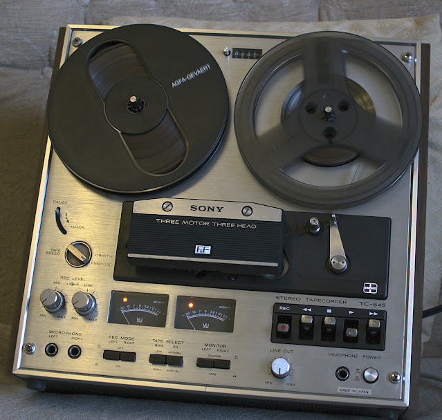
Sony TC-645 Reel to Reel

 Sony TC-645 Reel to Reel

This sentence in blue will be removed when this article is deemed to be finished. This is a work in progress. (July 2022)


Bought from ebay during July 2022.


Work completed on the 645 ...

  • Complete clean main audio circuit board, including vacuuming.
  • All mechanics and elbow joints freed and lubricated.
  • Idler Gear cleaned, evenly 'roughed up' by rolling on to grit paper, and later Rubber Renue applied.
  • All switches and potentiomters cleaned with Servisol Super 10 or direct equivalent.
  • Complete electrolytic capacitor replacement - on audio board, bias oscillator, and power supply unit.

    All capacitors and transistors in the
    bias oscillator were also replaced.
    Pictured with original components.
     
  • Complete transistor replacement - mainly using KSC1845-FTA, and KSC1815-GR where appropriate.


  • All three motor start/run capacitors replaced.
  • All switching capacitors replaced.
  • Recording of high frequency audio compression and, or distortion fixed. (A pre-emphasis modification)
  • Reel brake issues for supply and take up reels fixed.
  • The groung rail on the recording audio section was not earthed, and so it exhibited a floating potential of about 22mV/24mV. The effect of this was to add a dc (erasing) bias to recordings through the record head. 

Unresolvable Issue?: Tape rubs on leftmost part of erase head during FF and RW. Unless I can get the tape lifter bar to lift higher, there is going to be no change here.

Erase head wear was noticeable when I bought the machine. I lapped the erase head to remove the wear marks.

Before.

After
 

I will return to this at a later date.

As can be seen, the tape is still in contact
with leftmost part of the erase head during
both rewind, and fast forward.

Reel Brake Pad Replacement

Reel braking was unsatisfactory, more successful on Fast Forward than Rewind. The old worn, and partially chemically perished pads were leaving marks on the surrounds of the tape recorder, so they had to be replaced.

I have found that cut-to-size chamois leather strips, bonded to doubled sided sticky tape is working well, and so far I've no reason to think that they will fail, at least not in the short term.


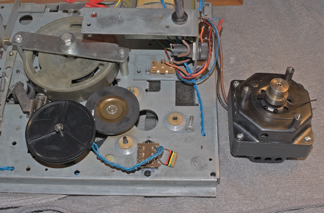
Users of the TC-645 with similar braking problems are advised to also check the T-section brake 'release line'. Here between the vertical arrows, the 'release line' must be allowed to easily rotate clockwise and anti-clockwise during operations.

Floating Ground within the Recording Audio Section

Buying and fixing old machines really throws up some quite unusual events. In this case, the ground rail was floating at around 22mV/24mV above the ground level of the playback audio section.

After carefully identifying all the grounding (0v) connection points on the main board, I eventually solved the issue of the recording head accidentally adding a small dc bias on to tape. The source of the problem appears to have been an inconsistent wired connection midboard.

Note: the capacitors on the solder side were only temporary.

Recording Pre-emphasis Modification

At the time of writing the TC-645 has not been playback level calibrated, nor playback EQ (de-emphasis) calibrated using a full track 1/4" reference tape.

The possibility of a pre-emphasis issue arose when observing severe high frequency compression/distortion on playback of speech and music which was recorded on this machine. If I lowered the recording level to ~ -20dB OVU, the machine was able to cleanly record high frequency speech or music sibilances without trouble, however above -20dB and the recording sounded 'dirty' at the top end.

More to follow later on the topic of pre-emphasis (record equalisation), and de-emphasis (playback equalisation) for this machine.


Full Track 1/4" Alignment Tape

I purchased an alignment tape which I need to help calibrate this tape recorder. It is certainly possible to intelligently estimate record levels, playback levels, and playback equalisation - so this step is not absolutely necessary to get your machine 'basically' working.

However, since I've put so much work into restoring this machine, it's only proper that I calibrate this TC-645 as far as possible to get the best out of the deck.

Before any calibration is undertaken, we must of course demagnetise all tape paths, followed by demagnetisation of the record and replay heads. The heads, and all other points where the tape is in contact, must be cleaned for reliable calibration.

Alignment here assumes that the tape guides are correct, that is - the guides 'guide' the tape across the heads correctly. And the heads are correctly height aligned - see the Sony TC-645 service manual.


The full track alignment tape above is for Sony reel to reel machines with a '0VU' field strength of 185 nWb/m, which by default is set to give 0.775v (rms) output at 400Hz, and is to be marked as '0VU' on the VU meters.

Note: 'n Wb/m' = nano-Webers per metre.

However, as modern tapes are capable of stronger magnetisation,  I wish to set '0VU' on this TC-645 to approximately 260 nWb/m. This means that I need to set the playback of 185 nWb/m to about -3dB on the VU scale, that is: 20·Log(185/260) = -2.96dB.


The procedure to achieve this was as follows: First turn the main output potentiomter fully clockwise on the front panel of the TC-645. Then run the reference tape at 7.5 ips (19cm/sec), and carefully turn the left channel (and later the right channel) playback 'PB' potentiometer so that the output of the deck reads 0.775 volts rms or approximately 1.1 volts peak on an oscilloscope. We would then normally adjust the VU meter calibration potentiometers to read '0VU', but on this occasion - set the VU meter levels to '-3dB' as shown above.

Playback Equalisation

The Sony's playback 'EQ' was (I believe) designed to follow the NAB playback curve, which I am led to believe is also called 'IEC2'?

Further along this full track reference tape there is a section which has a 400Hz tone, followed by a 10,000Hz tone in quick succession. I would then locate the playback (PB) EQ potentiometers (on the TC-645's circuit board) and trim so that both amplitudes of 400Hz and 10,000Hz are identical. In my case, I didn't need to, as I luckily guessed correctly!

However, according to the service manual this isn't the end of the subject - there are another set of frequencies to observe. They are: 40Hz, 80Hz, 7Khz, and 12.5Khz. On Sony's original J-19-F1 calibration tape similar tones are produced: 40Hz, 80Hz, 7Khz, and 10Khz, and fine EQ adjustments have to be made observing the playback levels of 40/80/7000/10000Hz and their deviation from the level obtained from 400Hz. The permittable deviations in dB units from the amplitude of 400Hz is specified in the TC-645 service manual.

They are ...

As can be seen, the service manual is somewhat ambiguous. What exactly is meant by '2 ± 2dB'? My interpretation is that it means +2dB ± 2dB, or 0dB to +4dB.

Okay, so then my procedure will be to adjust PB EQ so that 400Hz level equals the 10,000Hz level, then observe and make notes of the deviations when ...

(1)  10,000Hz level = 400Hz level ( 40Hz=  , 80=Hz  , 7Khz=  , 12.5Khz=  )
(2) 
10,000Hz level is +1dB of 400Hz level ( 40Hz=  , 80Hz=  , 7Khz=  , 12.5Khz=  )
(2)  10,000Hz level is -1dB of 400Hz level ( 40Hz=  , 80Hz=  , 7Khz=  , 12.5Khz=  )

Perfect playback flatness will not be obtained, so a compromise will have to be reached.

Frequency Response

Tape Speed: 3.75 ips or 9.5cm/sec. 

So far, using a Maxell UD 35-90 (35 micron, 90 minute) 1/4" tape which I purchased in 1989, at a recording level of -20dB (ref 260 nWb/m in this case), the frequency response stretches from 30Hz to 16,000Hz, at -3dB and less than 0dB respectively (ref: 400Hz). With a gentle rise beginning at around 2Khz/3Khz, peaking at about 7Khz (~2.5dB/+3dB) before dropping to +2dB at 10Khz, where finally sitting at over 16Khz at about 0dB. 

Increasing bias and I obtain 30Hz (-3dB) to 16Khz (-2dB), and a smaller rise is returned at 10Khz of about +1.5dB/2dB.  Observations were made on the oscilloscope, so they are only provisional at this moment.

Wow & Flutter

Tape Speed: 3.75 ips or 9.5cm/sec.

Using the now quite famous WFGUI.exe Windows program to compute wow & flutter figures, I recorded and played back a 3150Hz test tone at about -10dB. The returned value of W&F astonished me, as it was lower than factory specifications - between 0.03% and 0.04% wrms!

Possbily more to follow in the coming months .....

(Also subject to possible corrections, alterations, and amendments.)


cassettedeckman@gmail.com

Saturday, 30 July 2022

Sony TC-209SD

The Sony TC-209SD

This article is unfinished, and so this notice (in blue) will be remove when complete. (01/08/2022)

Well, this Sony deck is one I was always hoping to have - and here it is. Advertised as 'Faulty', but cosmetically in very good condition, I got it working within a few hours. The processes of fine tuning the TC-209SD will come later.

So, here it is in 95% ... 99% perfect working order - 


Initial Problems

  1. No feet
  2. Cassette loading tray was not accepting cassettes properly and so operating the deck was a bit risky. The cassette tape backlight diffuser had fallen down the back of the loading tray! Right-sided cassette loading mechanism screw had broken off - naturally the head of the screw was missing, as was the supporting collars.
  3. Tape up spool was not moving at all.
  4. Build up of sticky dirt on the circuit boards.
  5. The left channel VU meter was permanently deflected indicating a saturated level when the deck was ON!
  6. VU illumination needs brightening, right channel darker than left channel. 
  7. High frequency saturation - especially noticeable during speech or voice sibilances and drum cymbals.


More to follow .... 

Some Resoration Progress Photographs


All circuit boards were cleaned before operating the deck.
A new Motor Start/Run capacitor was fitted for 50Hz operation.
Calibration markings were made - shown on the right.

The main belt worked, but was slipping and so wow & flutter
figures were excessive - around 0.17% .. 0.21% wrms.

A temporary belt has been fitted, but the diameter is
really too short. Wow & flutter improved to
around 0.065% .. 0.095% wrms.

Here we see the flywheel which is about to be removed.


Probably dried grease was responsible for the
unresponsive take-up spool mechanism.

All freed using Servisol Super 10.


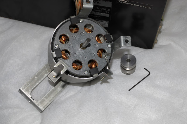
Lubricated the motor bearings, but saw no need
to replace them.
The allen key is only 1.27mm


Inactive Dolby

The Dolby ON switch wasn't invoking Dolby to encode, nor to decode!?


Why?: The answer was found by examining Pin 5 on the Dolby circuit board. It should be approximately: Dolby OFF: Pin 5 ~ 24v, Dolby ON: Pin 5 ~ 0v.

However, Pin 5 wasn't, the readings were approximately: Dolby OFF ~ 24v, Dolby ON ~ 9v ... 7v, and sometimes sporadically down to 3.2volts!
?

Source of Problem: The Switch Board.

The Dolby ON/OFF switch and its circuit board (below) was polluted with dirt, with perhaps an effective electrolyte (tiny amounts of conductive salts and moisture?) being present, and therefore low level conduction was occuring. The high impedance and effective non-loading of the Dolby ON/OFF point at Pin 5, meant that the conductive medium was subjecting Pin 5 to stray, and unwanted high potentials - thus keeping Dolby in an OFF state.

After cleaning this switch board, the Dolby ON/OFF voltages at Pin 5 are now 0.6v and 24v respectively.

In the process of cleaning the switch board.

Dolby circuit taken out from underneath.
All electrolytic capacitors have been replaced.

High Frequency Recording Saturation

While working on a Sony TC-645 reel to reel machine, high frequency record saturation was suspected when any high frequency audio content began to distort once I moved recordings above -20dB OVU. I had noticed this also on the TC-209SD, although not as severe. A solution to this became apparent as I pondered on the idea of attenuating the amount of pre-emphasis applied to recordings. This approach has seemingly proved successful on the TC-645, and so I decided to also reduce the amount of pre-emphasis on the TC-209SD.

The circuit below shows the audio output stage before the audio gets mixed with the bias 'carrier'. In the feedback loop of the TA7122AP voltage amplifier, there is a set of pre-emphasis filters for Normal, FeCr, and CrO2 tapes. Changing the polyester C151/C251 capacitors will shift the LCR circuit's impedance so that pre-emphasis can be adjusted for Normal tapes. Therefore lowering C151/251 by about 1/3, I was able to cut the amount of pre-emphasis and now the treble on playback is much cleaner and a joy to listen to.


New C151/C251 pre-emphasis polyester capacitors
soldered in from the solder side, so I can
remove them easily if required.
(Note: since this photo was taken, the capacitors
have been electrically isolated,
no short circuits are possible)


So far, I haven't fully calibrated this machine, so I cannot comment on the bigger picture as to whether this solution has affected overall frequency response and distortion. But so far, the TC-209SD is sounding good!

VU Meter Lighting

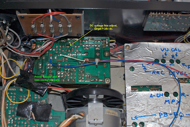
The lighting, in my opinion was insufficient. The old 'ac' circuit was removed, and replaced with 4 SM (surface mount) LEDs in series with a 2.2KΩ, 1/4 watt resistor. The circuit provides about 6mA of current to the SM LEDs, Kirchoff's Voltage Law written here is ... 24v(Supply) = 0.006(Amps) ✕ 2200(Ohms) + 4 2.7Volts.

The current rating for these diodes is about 20mA, but there is no need to have them shining so brightly.


VU meter lighting is better, and evenly distributed.

This blog is subject to additions, changes, corrections etc without notice.

03/09/2022.

cassettedeckman@gmail.com