REVOX B215 REPAIR: Automatically stops after 2 seconds
Quite possibly the Rolls-Royce of all cassette decks, along with the likes of the Nakamichi Dragon, ZX9 etc. This machine had a very heavy price tag to match its design and build excellence. This particular deck of mine was internally dated: "May 1985".

ISSUE: The B215 would stop 2 seconds after any command to Record/Play/FF/RW, so what was happening here? As I initially searched the internet for answers, I discovered that this was not an uncommon problem. Co-incidentally, I found no online solution either, apart from the usual 're-cap' suggestions which, let's be honest - isn't going to work all the time. I was on my own to find a solution.
Now it was time to find, download, and study the service manual preferably with circuits diagrams, then try to deduce the possible causes of this failure?
Problem: Machine stops after 2 seconds of operation. Why?
Investigation: The first idea that came to mind was to examine the tacho signals which were generated from infrared LEDs modulating concealed photo transistors at the reel-motor side of the cassette transport.
So how could I check this? Well, following the short ribbon transmission line ('Sensor Flex') from the cassette tape transport unit into the System Control Board, I was able to probe with an oscilloscope the integrity of the tacho data. All four binary tacho signals were working fine as I forced the deck to Fast Forward.

With that confirmed, I then need to test the shape of the pulses at both input and output of the LM339N Quad Comparator.
Examining the service manual circuit diagram, the LM339N is configured that it compares the tacho with a small reference voltage divider circuit (producing 2.5v), and will amplify to saturation (~5v) these 4 bits of data to the MAB 8440 Microcontroller if the tacho signal is greater than 2.5v.
The result of this investigation? The LM339N was failing. Two out of the four output bits were in error, they were permanently 'high' or at 5v.
 |
| Just some notes I made - wasn't initially intended for this blog. |
Comparitor Circuit in More Detail

 |
| Apparent circuit showing just one data bit of the four. |
How does the circuit work?
Each one of the photo transistors is activated by the infrared LEDs.
Two states exists:
QP=on, the circuit to the left of the red line becomes 'live' at approximately +5v. The V+ terminal input to the LM339N is also held 'high' (depends very approximately on the potential divider 5v*Δ47kΩ/[2.2kΩ+Δ47kΩ] setting) and so the LM339N saturates and so Vo ~ +5v.
QP=off, and the circuit to the left of the red line becomes effectively an open-circuit or at least very high impedance. At this moment the V+ terminal is approximately grounded, and the V- terminal drives the OP Amp comparitor into an inverting state, in this situation we have Vo ~ 0v.
I actually measured the (non-inverting) V+ terminal voltage when the 47 KΩ trimmer was set to about half way. During fast-forward operation (or RW or Play) it oscillated approximately between 0.1v and 4.9v. Varying the trimmer, I could force the V+ terminal input to zero - this would switch off any FF,RW, or Play action.
Back to the job of repair ...
Confident that this was at least one source of the problem I ordered some DIL sockets and a set of LM339N OP AMP chips.
As the original LM339N was soldered in, I had to be careful when desoldering. Of course I would have preferred if the chip was positioned via a DIL socket. The first and best approach to desoldering is NOT to desolder, but to cut the legs of the LM339N on the circuit board side only. A slow process, but one that works. After pulling the LM339N body away I proceeded to desolder or pull through the remaining legs. This way I can be almost sure that I won't over heat and lift the tracks - a nightmare scenario! The new DIL socket was soldered in, and the new LM339N positioned in place.
(Amendment: Of course I could have desoldered using a copper braid or solder wick, which is very effective and probably better, but at that time I didn't have any in stock. 20/4/2020)
 |
| System Control Board, track side. |
 |
| The top two DIL pins are redundant. |
As a precaution, I previously colour-coded the cables so was confident that I wasn't going to make any silly mistakes in putting this machine together. The next step was to switch on!
The Revox B215 now works! 👍

Recently I demagnetized the heads and capstans and ran through a Dolby Level 400Hz reference tape at 200nWb/m field strength ANSI standard. The meters read "0", which appears to be in accordance with the service manual. So even after 34 years, this machine still retained its playback level calibration!
Re-capping the boards is something I need to do, especially at the PSU stage, perhaps this autumn or winter? However, so far everything is working fine.
Some additional pictures:
| Frontside view of transport and the Sensor Ribbon. |
27/7/2019 (Subject to changes and corrections)
Revised: 28/7/2019, 8/04/2020.
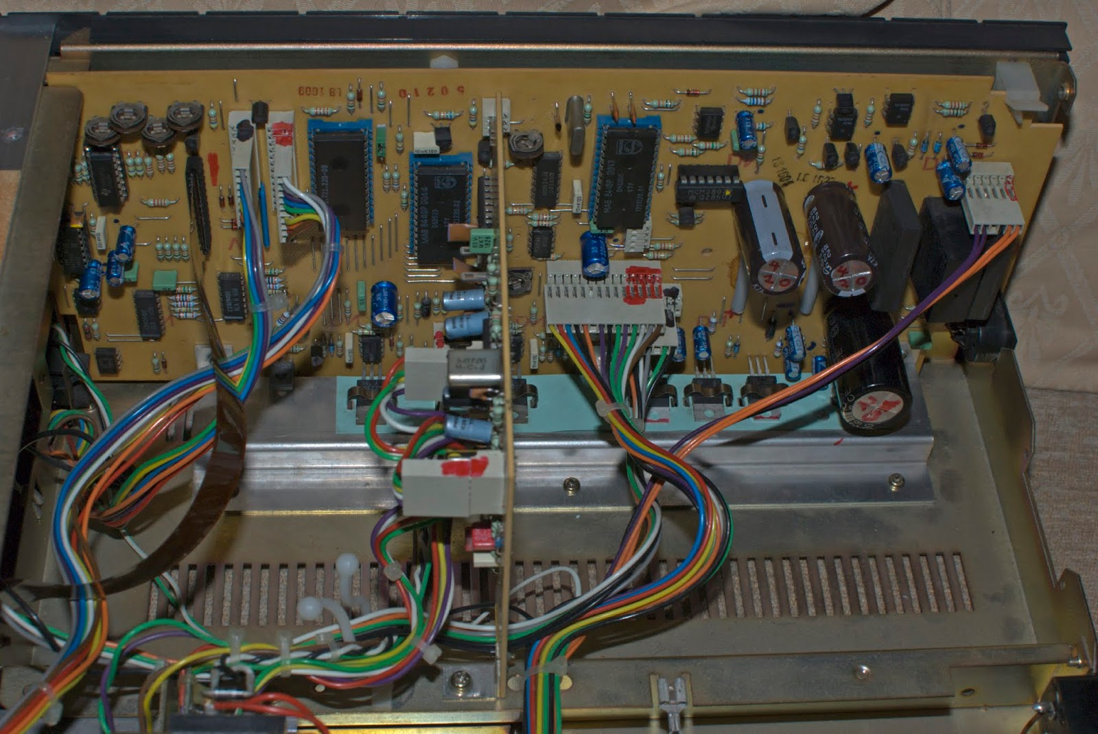
System Control (Main Board)
All the electrolytic capacitors and voltage regulators (LM317/LM337 series) have been replaced. Two axial 2200uF 40v-rated capacitors have been replaced with 2200uF 50v-rated radial types, simply because I haven't got any axial capacitors presently in stock.
9/04/2020.
May 2020: New axial capacitors now in circuit.
Minor additions: 27/04/2020, May 2020, 2/08/2020. 12/11/2020.
14/12/2021, 17/10/2022.
Also see ... Playback Calibration
Readers: This blogger page of mine receives more attention than any other. Those who visit this page may have problems with their Revox B215, if so was it the same problem as mine? You can send a comment below - it would be interesting to know how people got on with their repair work.