Friday 9 September 2022

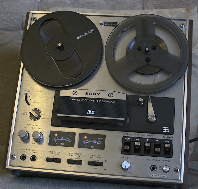
Sony TC-645 Reel to Reel

 Sony TC-645 Reel to Reel

This sentence in blue will be removed when this article is deemed to be finished. This is a work in progress. (July 2022)


Bought from ebay during July 2022.


Work completed on the 645 ...

  • Complete clean main audio circuit board, including vacuuming.
  • All mechanics and elbow joints freed and lubricated.
  • Idler Gear cleaned, evenly 'roughed up' by rolling on to grit paper, and later Rubber Renue applied.
  • All switches and potentiomters cleaned with Servisol Super 10 or direct equivalent.
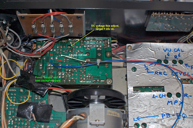
  • Complete electrolytic capacitor replacement - on audio board, bias oscillator, and power supply unit.

    All capacitors and transistors in the
    bias oscillator were also replaced.
    Pictured with original components.
     
  • Complete transistor replacement - mainly using KSC1845-FTA, and KSC1815-GR where appropriate.


  • All three motor start/run capacitors replaced.
  • All switching capacitors replaced.
  • Recording of high frequency audio compression and, or distortion fixed. (A pre-emphasis modification)
  • Reel brake issues for supply and take up reels fixed.
  • The groung rail on the recording audio section was not earthed, and so it exhibited a floating potential of about 22mV/24mV. The effect of this was to add a dc (erasing) bias to recordings through the record head. 

Unresolvable Issue?: Tape rubs on leftmost part of erase head during FF and RW. Unless I can get the tape lifter bar to lift higher, there is going to be no change here.

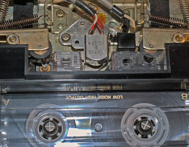
Erase head wear was noticeable when I bought the machine. I lapped the erase head to remove the wear marks.

Before.

After
 

I will return to this at a later date.

As can be seen, the tape is still in contact
with leftmost part of the erase head during
both rewind, and fast forward.

Reel Brake Pad Replacement

Reel braking was unsatisfactory, more successful on Fast Forward than Rewind. The old worn, and partially chemically perished pads were leaving marks on the surrounds of the tape recorder, so they had to be replaced.

I have found that cut-to-size chamois leather strips, bonded to doubled sided sticky tape is working well, and so far I've no reason to think that they will fail, at least not in the short term.


Users of the TC-645 with similar braking problems are advised to also check the T-section brake 'release line'. Here between the vertical arrows, the 'release line' must be allowed to easily rotate clockwise and anti-clockwise during operations.

Floating Ground within the Recording Audio Section

Buying and fixing old machines really throws up some quite unusual events. In this case, the ground rail was floating at around 22mV/24mV above the ground level of the playback audio section.

After carefully identifying all the grounding (0v) connection points on the main board, I eventually solved the issue of the recording head accidentally adding a small dc bias on to tape. The source of the problem appears to have been an inconsistent wired connection midboard.

Note: the capacitors on the solder side were only temporary.

Recording Pre-emphasis Modification

At the time of writing the TC-645 has not been playback level calibrated, nor playback EQ (de-emphasis) calibrated using a full track 1/4" reference tape.

The possibility of a pre-emphasis issue arose when observing severe high frequency compression/distortion on playback of speech and music which was recorded on this machine. If I lowered the recording level to ~ -20dB OVU, the machine was able to cleanly record high frequency speech or music sibilances without trouble, however above -20dB and the recording sounded 'dirty' at the top end.

More to follow later on the topic of pre-emphasis (record equalisation), and de-emphasis (playback equalisation) for this machine.


Full Track 1/4" Alignment Tape

I purchased an alignment tape which I need to help calibrate this tape recorder. It is certainly possible to intelligently estimate record levels, playback levels, and playback equalisation - so this step is not absolutely necessary to get your machine 'basically' working.

However, since I've put so much work into restoring this machine, it's only proper that I calibrate this TC-645 as far as possible to get the best out of the deck.

Before any calibration is undertaken, we must of course demagnetise all tape paths, followed by demagnetisation of the record and replay heads. The heads, and all other points where the tape is in contact, must be cleaned for reliable calibration.

Alignment here assumes that the tape guides are correct, that is - the guides 'guide' the tape across the heads correctly. And the heads are correctly height aligned - see the Sony TC-645 service manual.


The full track alignment tape above is for Sony reel to reel machines with a '0VU' field strength of 185 nWb/m, which by default is set to give 0.775v (rms) output at 400Hz, and is to be marked as '0VU' on the VU meters.

Note: 'n Wb/m' = nano-Webers per metre.

However, as modern tapes are capable of stronger magnetisation,  I wish to set '0VU' on this TC-645 to approximately 260 nWb/m. This means that I need to set the playback of 185 nWb/m to about -3dB on the VU scale, that is: 20·Log(185/260) = -2.96dB.


The procedure to achieve this was as follows: First turn the main output potentiomter fully clockwise on the front panel of the TC-645. Then run the reference tape at 7.5 ips (19cm/sec), and carefully turn the left channel (and later the right channel) playback 'PB' potentiometer so that the output of the deck reads 0.775 volts rms or approximately 1.1 volts peak on an oscilloscope. We would then normally adjust the VU meter calibration potentiometers to read '0VU', but on this occasion - set the VU meter levels to '-3dB' as shown above.

Playback Equalisation

The Sony's playback 'EQ' was (I believe) designed to follow the NAB playback curve, which I am led to believe is also called 'IEC2'?

Further along this full track reference tape there is a section which has a 400Hz tone, followed by a 10,000Hz tone in quick succession. I would then locate the playback (PB) EQ potentiometers (on the TC-645's circuit board) and trim so that both amplitudes of 400Hz and 10,000Hz are identical. In my case, I didn't need to, as I luckily guessed correctly!

However, according to the service manual this isn't the end of the subject - there are another set of frequencies to observe. They are: 40Hz, 80Hz, 7Khz, and 12.5Khz. On Sony's original J-19-F1 calibration tape similar tones are produced: 40Hz, 80Hz, 7Khz, and 10Khz, and fine EQ adjustments have to be made observing the playback levels of 40/80/7000/10000Hz and their deviation from the level obtained from 400Hz. The permittable deviations in dB units from the amplitude of 400Hz is specified in the TC-645 service manual.

They are ...

As can be seen, the service manual is somewhat ambiguous. What exactly is meant by '2 ± 2dB'? My interpretation is that it means +2dB ± 2dB, or 0dB to +4dB.

Okay, so then my procedure will be to adjust PB EQ so that 400Hz level equals the 10,000Hz level, then observe and make notes of the deviations when ...

(1)  10,000Hz level = 400Hz level ( 40Hz=  , 80=Hz  , 7Khz=  , 12.5Khz=  )
(2) 
10,000Hz level is +1dB of 400Hz level ( 40Hz=  , 80Hz=  , 7Khz=  , 12.5Khz=  )
(2)  10,000Hz level is -1dB of 400Hz level ( 40Hz=  , 80Hz=  , 7Khz=  , 12.5Khz=  )

Perfect playback flatness will not be obtained, so a compromise will have to be reached.

Frequency Response

Tape Speed: 3.75 ips or 9.5cm/sec. 

So far, using a Maxell UD 35-90 (35 micron, 90 minute) 1/4" tape which I purchased in 1989, at a recording level of -20dB (ref 260 nWb/m in this case), the frequency response stretches from 30Hz to 16,000Hz, at -3dB and less than 0dB respectively (ref: 400Hz). With a gentle rise beginning at around 2Khz/3Khz, peaking at about 7Khz (~2.5dB/+3dB) before dropping to +2dB at 10Khz, where finally sitting at over 16Khz at about 0dB. 

Increasing bias and I obtain 30Hz (-3dB) to 16Khz (-2dB), and a smaller rise is returned at 10Khz of about +1.5dB/2dB.  Observations were made on the oscilloscope, so they are only provisional at this moment.

Wow & Flutter

Tape Speed: 3.75 ips or 9.5cm/sec.

Using the now quite famous WFGUI.exe Windows program to compute wow & flutter figures, I recorded and played back a 3150Hz test tone at about -10dB. The returned value of W&F astonished me, as it was lower than factory specifications - between 0.03% and 0.04% wrms!

Possbily more to follow in the coming months .....

(Also subject to possible corrections, alterations, and amendments.)


cassettedeckman@gmail.com
Saturday 30 July 2022

Sony TC-209SD

The Sony TC-209SD

This article is unfinished, and so this notice (in blue) will be remove when complete. (01/08/2022)

Well, this Sony deck is one I was always hoping to have - and here it is. Advertised as 'Faulty', but cosmetically in very good condition, I got it working within a few hours. The processes of fine tuning the TC-209SD will come later.

So, here it is in 95% ... 99% perfect working order - 


Initial Problems

  1. No feet
  2. Cassette loading tray was not accepting cassettes properly and so operating the deck was a bit risky. The cassette tape backlight diffuser had fallen down the back of the loading tray! Right-sided cassette loading mechanism screw had broken off - naturally the head of the screw was missing, as was the supporting collars.
  3. Tape up spool was not moving at all.
  4. Build up of sticky dirt on the circuit boards.
  5. The left channel VU meter was permanently deflected indicating a saturated level when the deck was ON!
  6. VU illumination needs brightening, right channel darker than left channel. 
  7. High frequency saturation - especially noticeable during speech or voice sibilances and drum cymbals.


More to follow .... 

Some Resoration Progress Photographs


All circuit boards were cleaned before operating the deck.
A new Motor Start/Run capacitor was fitted for 50Hz operation.
Calibration markings were made - shown on the right.

The main belt worked, but was slipping and so wow & flutter
figures were excessive - around 0.17% .. 0.21% wrms.

A temporary belt has been fitted, but the diameter is
really too short. Wow & flutter improved to
around 0.065% .. 0.095% wrms.

Here we see the flywheel which is about to be removed.


Probably dried grease was responsible for the
unresponsive take-up spool mechanism.

All freed using Servisol Super 10.


Lubricated the motor bearings, but saw no need
to replace them.
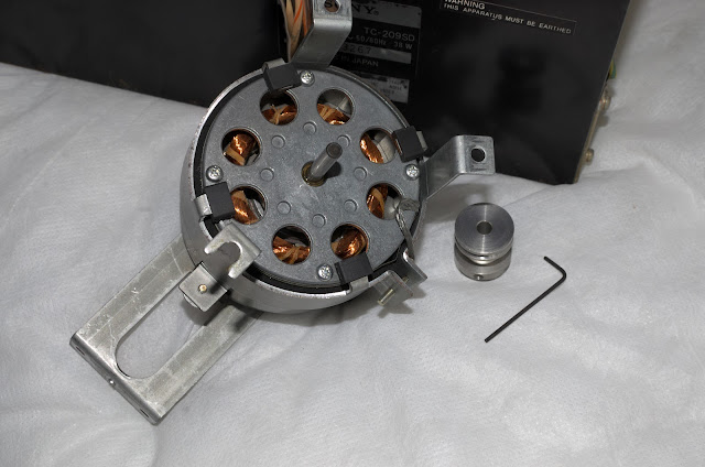
The allen key is only 1.27mm


Inactive Dolby

The Dolby ON switch wasn't invoking Dolby to encode, nor to decode!?


Why?: The answer was found by examining Pin 5 on the Dolby circuit board. It should be approximately: Dolby OFF: Pin 5 ~ 24v, Dolby ON: Pin 5 ~ 0v.

However, Pin 5 wasn't, the readings were approximately: Dolby OFF ~ 24v, Dolby ON ~ 9v ... 7v, and sometimes sporadically down to 3.2volts!
?

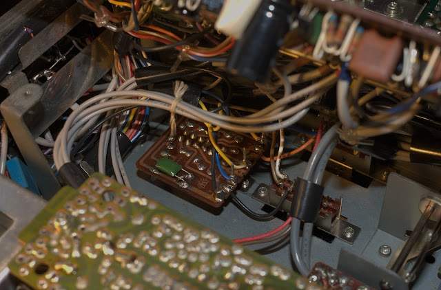
Source of Problem: The Switch Board.

The Dolby ON/OFF switch and its circuit board (below) was polluted with dirt, with perhaps an effective electrolyte (tiny amounts of conductive salts and moisture?) being present, and therefore low level conduction was occuring. The high impedance and effective non-loading of the Dolby ON/OFF point at Pin 5, meant that the conductive medium was subjecting Pin 5 to stray, and unwanted high potentials - thus keeping Dolby in an OFF state.

After cleaning this switch board, the Dolby ON/OFF voltages at Pin 5 are now 0.6v and 24v respectively.

In the process of cleaning the switch board.

Dolby circuit taken out from underneath.
All electrolytic capacitors have been replaced.

High Frequency Recording Saturation

While working on a Sony TC-645 reel to reel machine, high frequency record saturation was suspected when any high frequency audio content began to distort once I moved recordings above -20dB OVU. I had noticed this also on the TC-209SD, although not as severe. A solution to this became apparent as I pondered on the idea of attenuating the amount of pre-emphasis applied to recordings. This approach has seemingly proved successful on the TC-645, and so I decided to also reduce the amount of pre-emphasis on the TC-209SD.

The circuit below shows the audio output stage before the audio gets mixed with the bias 'carrier'. In the feedback loop of the TA7122AP voltage amplifier, there is a set of pre-emphasis filters for Normal, FeCr, and CrO2 tapes. Changing the polyester C151/C251 capacitors will shift the LCR circuit's impedance so that pre-emphasis can be adjusted for Normal tapes. Therefore lowering C151/251 by about 1/3, I was able to cut the amount of pre-emphasis and now the treble on playback is much cleaner and a joy to listen to.


New C151/C251 pre-emphasis polyester capacitors
soldered in from the solder side, so I can
remove them easily if required.
(Note: since this photo was taken, the capacitors
have been electrically isolated,
no short circuits are possible)


So far, I haven't fully calibrated this machine, so I cannot comment on the bigger picture as to whether this solution has affected overall frequency response and distortion. But so far, the TC-209SD is sounding good!

VU Meter Lighting

The lighting, in my opinion was insufficient. The old 'ac' circuit was removed, and replaced with 4 SM (surface mount) LEDs in series with a 2.2KΩ, 1/4 watt resistor. The circuit provides about 6mA of current to the SM LEDs, Kirchoff's Voltage Law written here is ... 24v(Supply) = 0.006(Amps) ✕ 2200(Ohms) + 4 2.7Volts.

The current rating for these diodes is about 20mA, but there is no need to have them shining so brightly.


VU meter lighting is better, and evenly distributed.

This blog is subject to additions, changes, corrections etc without notice.

03/09/2022.

cassettedeckman@gmail.com
Friday 8 July 2022

Sony TC-134SD Motor-Flywheel Alignment

Sony TC-134SD
Motor-Flywheel Alignment


The flat belt that is used on this model of the TC-134SD had a tendency to 'ride up' the flywheel, and would sometimes jump off during start-up.

The solution to this was to align both motor and flywheel axes to compliment each other so that the belt would remain stable and close to the centre of the flywheel.

In an ideal setup, both axes should be parallel. Unfortunately on this TC-134SD they weren't, although the error was minute.

Objective: The objective was to permanently set the angle of the motor so that the belt remained close to the centres of both motor pulley and the capstan's flywheel when running.

To achieve this I had to disassemble the motor from the deck and eventually insert a folded piece of card at the base, specifically at one side of the motor. This allowed the two axes to compliment each other and permit stable belt engagement between the motor and flywheel.   

In theory the two axes should be parallel - although camera lens
distortion in this picture gives the impression they are not.

I suspect they are still minutely out-of-parallel?

Note: The belt is seated close to the centres of
both motor pulley and capstan flywheel.

Operation is now very stable, even on start-up!


The arrow marks the area where a small piece
of folded card is used to tilt the motor.

All mechanics running smoothly.


**********************

Saturday 21 May 2022

Nakamichi 500 Dual Tracer

 The Goodmans SCD100/Nakamichi 500 Dual Tracer

Under the bonnet, this Goodmans SCD100 is 99% apparently a Nakamichi 500 Dual Tracer.

So what follows in this blogger page concerning the Goodmans SCD100 can also be applied to the Nakamichi 500, except that the '500' has a built in 400Hz tone generator for level calibration.

I bought the SCD100 second hand, it wasn't working properly. Since then, I've done quite a lot of work on this, and lot's more to do yet! I've got the machine operating in playback, record, fast forward, and rewind. Sounds very promising!  However, many minor repairs are required.

Initial Issues

  1. Internally the oils, and grease had dried up. (fixed)
  2. Mechanically, most functions were difficult to operate, and Pause had seized! (fixed)
  3. Motor speed was very inconsistent. (temporarily fixed)
  4. Noisey audio playback. (fixed)
  5. Intermittently - right channel extremely loud on playback (diagnosed - very probably a contact issue with the Record/Playback multi-switch not returning to Playback mode!?)
  6. VU Meters were moving sporadically. (fixed)
  7. Dolby instability/oscillations in left channel. (fixed)
  8. The SCD100 was recording 180° out of phase between left and right channels! Playback from pre-recorded tapes from third party machines were in phase - ie, normal.
    (fixed)
  9. Auto-stop not functioning. (Repaired using external circuit - 16/05/2022)

Later Considerations

  1. Professionally lap the record head?
  2. Audio alignments?
  3. An alternative motor controller, perhaps based on the AN6651 controller? 

When I get the time, I'll write about how I fixed (or not) the most challenging issues, ie, 3,5,7,8 and 9. 


Issue No 9: Auto Stop Fix

The original problem was that the auto-stop failed to work. After studying the circuit diagram from the service manual and opening up the auto-stop circuit many times, I concluded that the best solution would be to remove as much of the original circuit leaving only the working section in situe, and build an external circuit to drive it.


Take-up Spool motion detector and timing shown in light brown.

The inclusion of a flyback diode 1N4148 (or similar) was merely a precaution to protect Q601 when the reed switch closed, a reverse voltage (Vc601~ -15v) appears across the PN junction of the Q601 transistor.  Examining oscilloscope traces suggested that this 'spike' was at least 7.5v.

All transistors Q601/Q602/Q603 were replaced with 2SC2001.


The circuit was extensively tested 'offline' before applying it to the front end of the default relay switching circuit as operated by Q604.


Circuit Operation

Note the value of R604 has been increased to a maximum of 100kΩ
to help reduce an erroneous auto-stop state if the take up reel turns too slowly.
The auto-stop function takes about 2.5 seconds at R604 ~ 100kΩ.


When Play/RW/FF or Record+Play are pressed at least two events  happen ...

Mechanically:
The take up spool rotates and the reed switch will continuously open and close, 

Electrically: Q603 is switched ON via R605 10KΩ and 1R606 KΩ biasing, and regarding autostop timing - a potential of 15v is offered to the auto-stop circuit. 

At the point of t=0+Δt seconds, current through C601 (22uF) is at a maximum and Q601 is quickly switched ON.

This exponential decay current initiates an ON-period for Q601 for as long as Vbe ~ 0.6v or greater.


The graph above illustrates the exponential decay curve of the current through
resistor R602 (10KΩ), capacitor C601 (22uF), and R601 (3.3kΩ). Of particular interest is the potential difference across the 3.3kΩ load, ie Vbe of Q601.

The approximate value of Vbe vs Time is plotted above
- this is a reasonable approximation. In reality the base-emitter junction
of the Q601 possesses capacitance, and dynamic resistance, and so will also draw current. Typically PN junction capacitance is of the order of several pF - a tiny amount. This should not impact on the basic model I have used. The dynamic resistance however, may give rise to an increase in current at the R601/Vbe node.

There's potential drop across 10K
Ω to be considered. The value of Vbe for this short duration of time begins at approximately 3.7v (but could be as low as ½ of this figure?) and at sometime close to ½ second or less, Q601 will be turned OFF.

When Q601 =ON, then Q601 Vce ~ 0 (probably <0.2v), then C602 (47uF) is drained of charge quickly - this largely 'empties' C602.

When Q601=OFF, the collector-emitter of Q601 can be considered as an open circuit, and soon capacitor C602 begins to become charged again via R604. If the charging of C602 were not to be interrupted, it can reach a potential close to 15 volts.

During the time when Q601=OFF, the voltage across C602 rises until at about 0.6v + V(R606) this process then switches Q602=ON, which 'shorts' the Vbe PN junction of Q603 and forces Q603=OFF

Finally, now that Q603=OFF, the relay circuit and in particular the 'plunger' (that forces a mechanical STOP), is activated.

Transistor Q603 effectively switches power transistor (not shown) Q604 ON and OFF by controlling the current through R608, and hence Vbe of Q604.

STOP Action & Activation of the Solenoid Plunger: 
 
Not yet illustrated, is the circuit of a relay which activates a plunger - this pulls the Stop or Play/RW/FF release bar
 
When Q601=ON, Q603=ON, Q604=ON, Relay cannot force an OFF state.
When Q601=OFF, Q603=OFF, Q604=OFF, Relay can invoke an OFF state.
 
When the take-up spool is moving at a sufficient angular rate, the reed switch perpetually opens and closes, and so the charge on capacitor C602 never develops a large enough voltage to eventually activate the relay and force a STOP state.
 
Motor Speed
 
Initially, motor speed consistency was problematic. My initial thoughts were that brush to commutator contact was partially failing.


Internally, the motor had many tiny carbon deposites, all of which were removed. The commutator was also cleaned and roughed up with very fine emery paper. The spring action of the brush's sprung copper arms was a little suspicious, so I pushed them more towards the centre before reassembly.
 
The electrolytic capacitor was replaced, and the commutator was sprayed with Servisol Super 10. 
 
Note: great care and thought must be made when diassembling and re-assembling the motor as the permanent magnet ('field magnet') will pull and jerk the rotor and may damage the brushes. 
 
So far motor speed is consistent, but I'm not 100% confident as wear on the brushes is obvious.

29/05/2022: Possibly more on this deck to follow at a later date.

Monday 11 April 2022

Sony TC-161SD Later Model

 Sony TC-161SD (Later Model)


11/04/2022

A few weeks ago I bought another TC-161SD for 'spares' but then found that this machine had a different capstan flywheel design - very similar, if not identical to that employed on the later 'flagship' TC-177SD! 

I soon realised that this deck was too valuable to be used for 'parts' only!


Flywheel system of the later series of the TC-161SD.

The motor pulley and flywheel are connected via a flat belt,
not a square belted system


This initial photograph shows
the original motor start/run capacitor -
which can be seen top right corner.
 

Old Record/Replay Head

The deck was riddled with problems, mainly mechanical and possesed a record/playback head that appeared to be 'open circuit' in the left channel.

Taking the old head out of circuit did confirm that only the right channel was operating, while the left channel appeared to be open circuited! The head was now useless.


In the meantime I replaced the motor start/run capacitor, and later re-capped both the power supply and the auto-stop circuitary.

Replacement Head

The next task was to replace this with a third-party head.

I have a small stock of NOS heads, 'New Old Stock'.

The inductance of the replacement head is around 167mH, the TC-161SD's (~85Khz) bias voltage was currently around 31v peak.

Bias Currents

The new peak bias current will sit around 31/(2*3.142*85000*0.167) or ~ 347uA. Compared to 31/(2*3.142*85000*0.175) or ~ 331uA when the original PF145-3602's was in circuit.

These bias currents are tiny and virtually the same for either head. The audio current signal sits on this 85Khz bias 'carrier' is so small it will hardly register.

Please note - I've neglected head resistance in the calculations, as the inductance will dominate the value for the impedance at 85Khz.
 
New Head Mount

The NOS head was mounted on the original Sony head platform, but I had to first drill-out two head position locators which were employed to position the head correctly.

Both the old platform and the new head had their 'mating' surfaces 'roughed up' using 400 grit emery paper. Later the two were glued into place using Gorilla Glue, which 'cures' over a period of 24 hours. The two halves were held together 'still' under light pressure in a small vice - alignment was critical.

Alignment here being - that the head face and movement would be normal (90°) to the direction of the tape, and that the head stroke (depth) when Play was engaged, would not be excessive. Note - head height, tilt (zenith), and azimuth can be independently adjusted later.


New record/playback head secured on to the old platform.


The cured glue can be seen in its expanded state.

The glue also ran through the two drilled holes - out of shot.


TC-161SD Head Assembly


New head in operation.

Fully aligned - head height, tilt, and azimuth.

Excellent transportation.


************************************

11/04/2022: This blog/article is unfinished  .....
 
Pre-emphasis Change (04/12/2022)
 
Re-reading through this article again I soon realised that I had not modified the pre-emphasis curve for this later version of the TC-161SD cassette deck.
 
At some later date I hope to write up why I needed, and how I was able to reduce recording pre-emphasis for this and many other decks.

However, for now, here is the modification for this machine:


To access the pre-emphasis (Normal/CrO2) switch board, six screws and their respective switches had to be removed from the top side of the tape deck.
 

It was easier to solder the new components this side up, in case I need to remove them later.
 
Result: success!, the TC-161SD delivers nice clean voice sibilances and treble!
 
After this job was complete, the usual checks were made to ensure that previous playback levels and record levels had not changed?; they hadn't!  

After experimenting with the recording bias for both left and right channels by subjecting the recorder to white noise at about -20dB (or a little higher), I can report back that the frequency response for this 1972/1973 design deck on a 1980s TDK D C90 tape was slightly better than 40Hz ... 15,900Hz/16,500Hz at -3dB, left/right channel respectively. Reference: 1000Hz.
 
Random Induction Motor Images
  
These images were taken not long after I had bought the deck.


13/06/2023
New Drive Belt: With a 110mm (diameter) x 5mm (width) belt fitted, wow and flutter as measured on WFGUI.EXE measure somewhere between 0.045%-0.075% Weighted RMS.

cassettedeckman@gmail.com