The Sony TC-209SD
This article is unfinished, and so this notice (in blue) will be remove when complete. (01/08/2022)
Well, this Sony deck is one I was always hoping to have - and here it is. Advertised as 'Faulty', but cosmetically in very good condition, I got it working within a few hours. The processes of fine tuning the TC-209SD will come later.
So, here it is in 95% ... 99% perfect working order -
Initial Problems
- No feet
- Cassette loading tray was not accepting cassettes properly and so operating the deck was a bit risky. The cassette tape backlight diffuser had fallen down the back of the loading tray! Right-sided cassette loading mechanism screw had broken off - naturally the head of the screw was missing, as was the supporting collars.
- Tape up spool was not moving at all.
- Build up of sticky dirt on the circuit boards.
- The left channel VU meter was permanently deflected indicating a saturated level when the deck was ON!
- VU illumination needs brightening, right channel darker than left channel.
- High frequency saturation - especially noticeable during speech or voice sibilances and drum cymbals.
More to follow ....
Some Resoration Progress Photographs
 |
| All circuit boards were cleaned before operating the deck. A new Motor Start/Run capacitor was fitted for 50Hz operation. Calibration markings were made - shown on the right. |
A temporary belt has been fitted, but the diameter is
really too short. Wow & flutter improved to
around 0.065% .. 0.095% wrms.
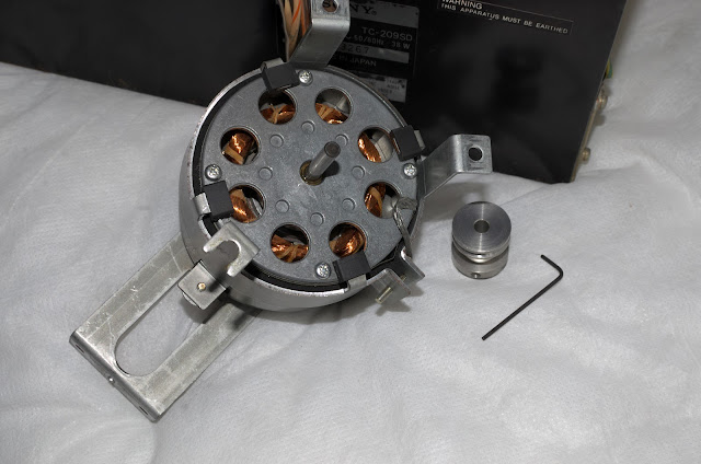
Here we see the flywheel which is about to be removed.
 |
| Probably dried grease was responsible for the unresponsive take-up spool mechanism. All freed using Servisol Super 10. |
 | |
| Lubricated the motor bearings, but saw no need to replace them. The allen key is only 1.27mm |
However, Pin 5 wasn't, the readings were approximately: Dolby OFF ~ 24v, Dolby ON ~ 9v ... 7v, and sometimes sporadically down to 3.2volts!?
Source of Problem: The Switch Board.
The Dolby ON/OFF switch and its circuit board (below) was polluted with dirt, with perhaps an effective electrolyte (tiny amounts of conductive salts and moisture?) being present, and therefore low level conduction was occuring. The high impedance and effective non-loading of the Dolby ON/OFF point at Pin 5, meant that the conductive medium was subjecting Pin 5 to stray, and unwanted high potentials - thus keeping Dolby in an OFF state.
After cleaning this switch board, the Dolby ON/OFF voltages at Pin 5 are now 0.6v and 24v respectively.
 |
| In the process of cleaning the switch board. |
 |
| Dolby circuit taken out from underneath. All electrolytic capacitors have been replaced. |
High Frequency Recording Saturation
While working on a Sony TC-645 reel to reel machine, high frequency record saturation was suspected when any high frequency audio content began to distort once I moved recordings above -20dB OVU. I had noticed this also on the TC-209SD, although not as severe. A solution to this became apparent as I pondered on the idea of attenuating the amount of pre-emphasis applied to recordings. This approach has seemingly proved successful on the TC-645, and so I decided to also reduce the amount of pre-emphasis on the TC-209SD.
The circuit below shows the audio output stage before the audio gets mixed with the bias 'carrier'. In the feedback loop of the TA7122AP voltage amplifier, there is a set of pre-emphasis filters for Normal, FeCr, and CrO2 tapes. Changing the polyester C151/C251 capacitors will shift the LCR circuit's impedance so that pre-emphasis can be adjusted for Normal tapes. Therefore lowering C151/251 by about 1/3, I was able to cut the amount of pre-emphasis and now the treble on playback is much cleaner and a joy to listen to.
 | ||
| New C151/C251 pre-emphasis polyester capacitors soldered in from the solder side, so I can remove them easily if required. (Note: since this photo was taken, the capacitors have been electrically isolated, no short circuits are possible) |
So far, I haven't fully calibrated this machine, so I cannot comment on the bigger picture as to whether this solution has affected overall frequency response and distortion. But so far, the TC-209SD is sounding good!
VU Meter Lighting
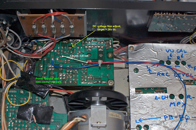
The lighting, in my opinion was insufficient. The old 'ac' circuit was removed, and replaced with 4 SM (surface mount) LEDs in series with a 2.2KΩ, 1/4 watt resistor. The circuit provides about 6mA of current to the SM LEDs, Kirchoff's Voltage Law written here is ... 24v(Supply) = 0.006(Amps) ✕ 2200(Ohms) + 4 ✕ 2.7Volts.
The current rating for these diodes is about 20mA, but there is no need to have them shining so brightly.
 |
| VU meter lighting is better, and evenly distributed. |
This blog is subject to additions, changes, corrections etc without notice.
03/09/2022.
cassettedeckman@gmail.com


No comments:
Post a Comment