Trio/Kenwood KA-6100
Intergrated Amplifier
Another new purchase.

If any work on this amplifier is pending, then I'll write about it here.
Trio/Kenwood KA-6100
Intergrated Amplifier
Another new purchase.
If any work on this amplifier is pending, then I'll write about it here.
The AKAI AM-2400
Integrated Amplifier
Another ebay purchase at a good price.
All that was required was to dry-brush and vacuum-clean the inside of the amplifier, contact-clean the switches, apply lubrication to the switch action, and carefully wash the fascia, controls, and 'work the buttons' with diluted metal polish.
Apart from a few scratches, it's looking good.

Tone Control Board
I've replaced all the capacitors on the tone board; there were (and still are) electrolytic capacitors valued at 0.15uF and 0.22uF that don't need to be electrolytic. The said board was also re-transistorized; replacing the 2SC1213 NPN types with Motorola BC549B types. I am not advising anyone reading this to do the same, although (probably) the 2SC1845/KSC1845 would be a better solution, as the pins are configured in a similar (but reversed) way as the originals. My choice was purely based on my large stock of BC549Bs, and since I wanted to lower my stock in numbers, that's what I did.
I replaced these 2SC1213 transistors in the hope that low level background tone amplifier transistor and general thermal noise could be reduced - you can hear it with headphones when the volume potentiometer has been turned fully anti-clockwise. Later, I hope to replace all carbon resistors within the said board with metal film types. Hopefully this will reduce tone control amplifier noise?
The reader may get the impression that this amplifier is 'noisy', the truth is - it is not. The reason I can hear the thermal or Johnson Noise when the volume potentiometer is turned fully anti-clockwise is that the volume control sits before this audio stage! This means that the push-pull Class A-B power amplifier is receiving the full output of the tone board all the time, and that includes any natural thermal noise.
The only difference the current transistor replacements made are - noise is balanced between left and right, where previously it was more leaning towards the right side. Subjectively, the noise may indeed be lower?, but it's difficult to confirm absolutely.
Below we see the original service manual schematic highlighting the 2SC1222 series as the main audio transistors.
 |
| The tone amplifier employs a mixture of Current-Shunt, and a switchable Voltage-Series feedback topography. |
 |
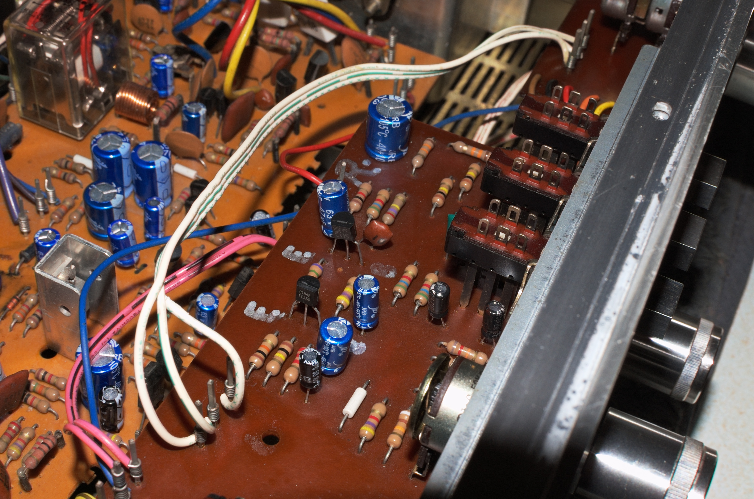
| Original 2SC1213 transistors on the tone control board |

 |
| Note - the alignment of the BC549B on the tone board. |
 |
| Note - the necessary alignment of the BC549B on the tone board. |
Tone Control Board Alterations: (22/09/2022)
Sometime later, there were random 'noise bursts' in the left channel at a very low level, almost imperceptible, but nevertheless they persisted. Later I discovered the apparent source - a dirty contact within the main volume potentiometer VR2, and after cleaning this (again), the problem disappeared.
Just prior to this work I decided to exchange the BC549B transistors for Fairchild's KSC1845FTA, and KSC1815-GR on this board.
Now we have: TR1=KSC1845, and TR2=KSC1815
Also of note, the main audio board which serves the power amplifier and voltage regulation has been re-populated with new electrolytic capacitors.
23/09/2023. This page may be updated if anything relevant to the working, or modifications to the AKAI AM-2400 are undertaken.
The Kenwood KT-7500
Stereo FM/AM Tuner
I recently bought this to add to my interest in HiFi receivers and tuners.
The Kenwood KT-7500 is a beautifully engineered and finished piece of HiFi with a gorgeous fascia and controls, and of course high-end performance to match.
This particular version of the KT-7500 is slightly unusual in that there are two switchable de-emphasis configurations to choose from: 25µs and 75µs time constants; symbolically represented by 𝛕. If a tuner is going to give you a choice, then I would have expected both 50µs and 75µs time constants, not 25µs and 75µs!?
The time constant parameter 𝛕, is an accepted convention when describing 'corner frequencies' in the playback of a first-order, low-pass filter frequency response. Each time constant 𝛕 is directly linked to a corner frequency fc.
Here in the UK, the playback de-emphasis curve adheres to a time constant of 50µs, that is 𝛕 = 50/1000000 seconds, whereas, in the United States and Canada, they employ the 75µs time constant.
Therefore, it is quite possible that this KT-7500 was purchased in the US or Canada back in the late 1970s? I say this since 25µs was intended to be used for Dolby encoded broadcasts in the United States, possibly Canada too? For this to work correctly, a Dolby outboard would be required?
An explanation of de-emphasis, and the associated time constant will be explained at, or near the end of this article.
The KT-7500 in its Wooden Housing:

Opening up the KT-7500 reveals a beautifully laid out circuit.

Highlighted above in white is the final low-pass de-emphasis circuit that needs to be modified so that both 50µs and 75µs time constants are easily accessed, at present I've only 25µs (for a Dolby outboard?) or 75µs (United States) to choose from.
Observe below, a picture taken for the original advert by the seller, and the limited choice: 75µs (US or Canada) or 25µs (Dolby encoding) de-emphasis setting.
 | |
Identifying De-emphasis Stages
Studying the schematic for the KT-7500, we are able to track down the output stages, and identify the de-emphasis low-pass circuit.

Studying the circuit diagram reveals that a NJM4558 dual OP Amp has been used in the final stages of audio post-processing; that is FM de-emphasis.
The OP Amp appears to be configured in a non-inverting, first-order low-pass state. Similar to that shown below -

Av(ω) = 1 + Zf(ω)/R
Where Zf(ω) is the impedance of the parallel network containing the 33kΩ resistor and the 750pF (and, or the 1500pF) capacitance. The R is the 2kΩ resistance as shown above.
This voltage amplifier's gain is frequency dependent, but can easily act as a voltage follower if Zf→0Ω; in that case the gain is simply unity, ie 1.
However, returning to our low pass de-emphasis amplifier and filter - in terms of the resistive and capacitive components, the complex form of the voltage gain of the OP Amp in this non-inverting arrangement is:

Where Rf = 33000Ω, C = 750pF or 2250pF, and R1 = 2kΩ.
Note: In the KT-7500, C is actually switchable between 750pF and (750+1500)pF.
Also, be mindful that periodic frequency f (Hz) is related to angular frequency ω=2𝝿f (radians/second), or f=2𝝿/ω.
In the above 'complex' form, both voltage gain and input vs output phase shift can be analyzed.
In an attempt to keep this write up as simple as possible, the mathematical issues of derivation of formulae are going to be by-passed.
Computing OP AMP Gain Av(f) vs Frequency (Hz)
Applying a complex conjugate operator to the above expression, and we have ...


 |
| Frequency Response Curves for CR value of: C x R = 50µs |
Corner Frequency and Time Constant
The corner frequency is that frequency f, for which
2𝝿fCR = 1,
or
f = 1/{2𝝿CR} Hz.
The gain then becomes .....

Under these conditions, and without the '1' term, the gain is (Rf/R1)×(1/√2) or -3dB below its maximum value. However, because the gain for this OP Amp configuraton is Av = 1 + Zf/R, the '1' offsets this calculation a little.
The time constant 𝛕 mentioned earlier is generally derived from RC networks and their ability to charge or discharge, and in particular - the initial rate at which charging/discharging occurs on response to a voltage step function.
𝛕 definition: If this initial rate of charge were to be maintained, then the time taken for the capacitor to become fully charged or discharged is equal to: C x R seconds.
That is ...
𝛕=CR
The reader may have already deduced that frequency f and 𝛕 are related, that is, at the corner frequency fc: fc = 1/{2𝝿𝛕}.
UK FM De-emphasis
Here in the UK, the 50µs de-emphasis time constant 𝛕 is employed, it is directly related to a de-emphasis corner frequency.
fc = 1/{2𝝿ᐧ50µs} = 1000000/{2𝝿ᐧ50} = 3183Hz.
In the context of the KT-7500, and to obtain 𝛕=50µs, C needs to be 1500pF, neglecting component tolerances, the actual values of CR used above gives ...
𝛕=1500pF*33KΩ = 49.5µs
or
fc = 1000000/{2𝝿ᐧ49.5} = 3215Hz.
Now examine the above plot to confirm the -3dB drop at approximately 3183Hz. This equates to (1/√2)*17.5 at 3183Hz.
United States/Canadian De-emphasis
In the US and Canada, 𝛕=75µs, that is ...
fc = 1000000/{