SONY ST-SA3ES Attempted Repairs
I bought this Sony tuner back in 2005, although within 12 months the tuner was hinting that it had a fault - an intermittent albeit short noise burst, followed sometimes by loss of signal.
Added to this problem, one of the MPX LPF filters appeared to have shorted, so I had to electrically bi-pass this part of the circuit to get the set working again. Effectively, I believe one channel is multiplex filtered (eliminating the FM Stereo 19Khz pilot tone), while the other is not.
Already compounded with these problems, the frequency display also over-reads by +0.05Mhz.
 |
| Display should read: 90.50MHz |
(a) Intermittent noise bursts/signal losses (now random, but seemingly a simple connection issue?)
(b) Left channel output is now not multiplex filtered, ie 19Khz Pilot Tone 'leaks' through.
(c) Frequency display, in error by +0.05Mhz.
To date, I have replaced ...
(a) The Sanyo multi-voltage regulator in the power supply.
(b) Bi-passed MPX filter air-core transformer/choke. (To be re-installed once I find a replacement)
(c) Replaced some electrolytic capacitors on the main board.
What a mess!
Attempted Diagnosis of Sporadic Loss of Signal
The other day, I finally de-soldered the delicate Front End tuner section, hoping to find some indication of why the tuner delivers occasional sporadic noise bursts, and random loss of signal.
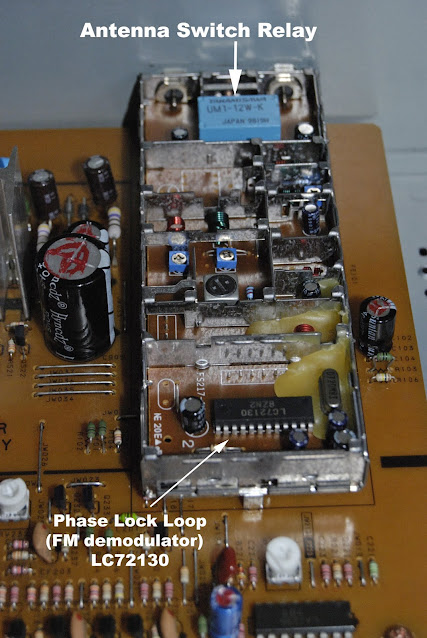
Thoughts were aimed towards (a) a faulty Phase Lock Loop (PLL) circuit?, (b) a simple loss of RF signal connection within the Front End Tuner section?
 |
| Top right in blue: the antenna A/B relay switch. |
The idea of a noisy antenna A/B relay switch had crossed my mind, and so I took the ambitious step of opening the front end tuner, which also contains a heterodyne mixer, and a phase lock loop unit.
Nothing obviously at fault from above, I then de-soldered the said circuit and examined the underside.
I had a hunch that there is a problem with basic signal circuitry, so I mulled over the underside of the front-end unit. As illustrated above there are two FM antenna inputs, and the apparent common RF point to which either one of the antennas will be connected depending on the options on the display panel of the ST-SA3ES.
After some thoughts I made decision to short-circuit the common input RF point to antenna A, so that this antenna will always be 'on'. In this scenario, the antenna A/B relay is partially ineffective, although still physically active - the ST-SA3ES can still receive RF input from either: A and not B, or A and B.
After reassembling carefully, the tuner appears to be working without loss of signal, although I think I did detect one of those noise bursts which only last for a split second?
So far, and many hours later, the Sony ST-SA3ES tuner is working well, and is stable in operation. The other issues like the lack of a LPF LC circuit in the MPX section, and a display error of +0.05Mhz will have to wait until I find a solution for them.
Looks like this loss of signal is not an isolated incident, it is spoken of here .... https://forums.digitalspy.com/discussion/1791340/sony-narrow-band-tuner-same-problems-with-both
19/10/2019
21/10/2019: While the RF signal cut-out (much like unplugging the antenna) seems to have been stopped, the occasional low level rain-like noises (sometimes surface, as if there was a build up of charge which then finally discharges. These two faults could conceivably be two separate issues? The latter does sound like a chipset partially failing, perhaps the PLL unit?
24/10/2019: After deciding at one last go, I de-soldered the RF Front End again from the main board, and re-capped the Front End unit, except for one electrolyic capacitor. I decided to replace them so that I could at least identify which were the probable components of this rain-like (mono) noise that is experienced usually after switching on. The noise soon disappears after a few minutes, but may re-surface from time to time.
Desoldering this, and the capacitors from the unit was no easy job - the new capacitors have been marked in red.
I think I can confidently say that the source of the random rain-like noise can be sourced at the phase-lock-loop chip, or the circuit connection surounding it. Once the noise had gone, I can often make it return by pressing the chip with my finger - so it has to be the chip, or its immediate surrounds?
 |
| before re-capping, the LC72130 PLL - the source of the rain-like noise after switch on? |
Sony recommends replacing the unit if problems occur, I can see why!
28/10/2019: The tuner to my surprise has now decided not to receive signals, identical in sound to pulling the antenna out. The front end is now effectively an open-circuit - all that work for nothing!
Time I think to scrap the ST-SA3ES completely?
6/11/2019: I have pulled the circuit board out, and will salvage some components from it. The Phase Lock Loop chip must be faulty? I don't think I shall bother to replace it, after all, I cannot be absolutely certain what the issue is. This type of fault has been recorded several times on the internet including a Russian website - no definitive solution found it seems anywhere?
******************************************************


