Monday, 26 August 2024

Sanyo RD 4600 - Direct Drive Capstan Cassette Deck

Sanyo RD 4600


Advertised on ebay (uk) as not working I won the bid and took my chance with this purchase.

I could see that the VU meters were problematic, and indeed upon opening up the meter casing I could identify that the left channel VU meter had its loading/return spring partially buckled.

An attempt was made to salvage the VU meter by very carefully de-buckling the return spring and then strengthening the weak area with ultraviolet light glue - the process worked very well. So now both meters work.

The VU Meters before they were partially repaired.

Initial Findings
 

Before any work on the meters was done, the machine arrived near 'dead' - the meter lamps lit up, but nothing else happened.

For anyone not familiar with the RD 4600, I'll issue a warning - this cassette deck is not 'repair friendly'. It took me some time to decipher how open up the machine.


Power Supply Unit

Observing the PSU, it was noted that a push-on cable had come away and returning this to its intended point, the motor began to rotate! At last, the deck was 'alive'.

At this point the deck would playback tapes, although take up spool  torque was low, and RW/FF didn't work consistently. These faults were soon taken care of via disassembly of the cassette transport and cleaning.

The next and obvious job was to re-populate the PSU with new electrolytic capacitors.


Sanyo RD 4600 PSU, and Bias Oscillator Board.
Image shows the unit partially re-capped.
Later - many of the other components were
also replaced.


This board not only acts as a power supply unit (PSU), but also for two sources of DC supply voltage - a regulated supply at about 19v, and nonregulated at about 24v.

The said board also contains the bias oscillator, bias current control to match bias to the tapes, and a bias trap. The purpose of the trap is to filter out the bias high frequency and relatively high bias voltage from the audio circuits.


Play Mode

In PLAY mode, the deck would sometimes not operate - one source of this problem was a sticky PLAY solenoid. All mechanisms were cleaned with IPA and a Servisol Super 10 equivalent.

Another issue that surfaced was that pressing PLAY didn't always activate the full driving voltage (approx 12v DC) across the solenoid to operate the PLAY mechanism. I originally thought there may be a problem with the solenoid, but it transpired that the PLAY relay internal contacts were probably and partially corroded? All relays associated with Record/Play/Pause/Cassette-Eject were replaced.

To identify this, studying the service manual's circuit diagram was neccessary and the returned hypothesis was that relay contacts were probably to blame.


The DC driving voltage for the PLAY solenoid is approximately 12v, but under load conditions this didn't happen? My thinking was that - the relay contacts were offering (internally) high impedance to the circuit. This explained why the solenoid did not activate - too much voltage drop across the corroded contacts, hence not enough current to drive the solenoid.

RD 4600 with New OMRON G5LE-14 relays


Record Bias Noise in Right Channel

The original head recorded and played back fine, no problems except that there was low-level, but noticeable random bursts of extra white/pink noise (bias noise) in the right channel.

After studying most or all of the possibilities, it was concluded that the original Sanyo head was faulty; quite why it did this I don't know?, but similar occurances have happened to other hard-wearing heads like - the Sony Ferrite & Ferrite heads.

Gap erosion is a subject that is talked about on the Tapeheads forum, and I'm assuming that this just might be one of the negative 'spin offs' from this?

I was reluctant to swap the head, but I did eventually. The replacement was a (Chinese made?) DYNY62.


Estimation of Record Head Bias Current

Firstly we measure head inductances, the general consensus seems to be - measure at 10Khz, so we have ...

  • Sanyo T-159 D5A5: Right~165.8mH, Left~163.2mH.
  • DYNY62: Right~126.7mH, Left~120.5mH.

From this, the head impedance, and hence AC bias current generated at the bias operating frequency of 100Khz can be estimated.

Making the assumption that bias voltage is about 15v to 20v rms, then ...

From basic Ohm's Law: I = V/Z(𝟂), where the impedance Z(𝟂) is almost exclusively inductive, we can estimate the impedance due to the inductive reactance X at 100,000Hz, and later the bias current.

Bias Current: I ≅ V/X

But X = 𝟂L = 2πfL = 2x3.14159x10^5*L

Where L is the inductance in Henries. 

Then for Sanyo (Right Channel) ...

15/(2πx10^5*0.166) to 20
/(2πx10^5*0.166), or 144µA to 192µA.

And for DYNY62 (Right Channel) ...

15/(2πx10^5*0.127) to 20
/(2πx10^5*0.127), or 188µA to 251µA.


These bias current are low by default and comparing, they are not radically different.

The effective impedances at audio frequencies will be much less, but so too will the audio signals. Typically, audio AC voltage signals will be in the
µV range, and possibly a few mV at higher frequencies due to recording pre-emphasis.

Original Sanyo T-159 D5A5 Record/PB Head.


New Head in Circuit.

New DYNY62 REC/PB Head During Testing

Fitting the head was not so simple, the original Sanyo head and platform screw holes are postioned differently from other 'standard' two-head cassette decks. The rightmost new head's guide hole had to be elongated by about 1mm before a near centre line for the head could be established. In fact, more work may be done on this later. Head penetration is unaffected.

Wow & Flutter (Initial tests)

With the original pinch roller, wow & flutter figures as measured by WFGUI indicate figures almost consistently under 0.08% wrms.


TDK D46 Initial Tests


These indicate the record/playback frequency response at -20dB (ref: 0VU) is better than 40Hz to 15,500Khz (±3dB). And Total Harmonic Distortion at +6dB (Ref: 0VU) in the region of 1%. (I will update these figures when the machine is considered to be completely restored)

Before a 'new' head was fitted, the audio board was almost completely re-capped, and most of the original NPN and PNP transistors were replaced by KSA1845-FTA/C1815-GR/2SA992/2SC2001 types where required.

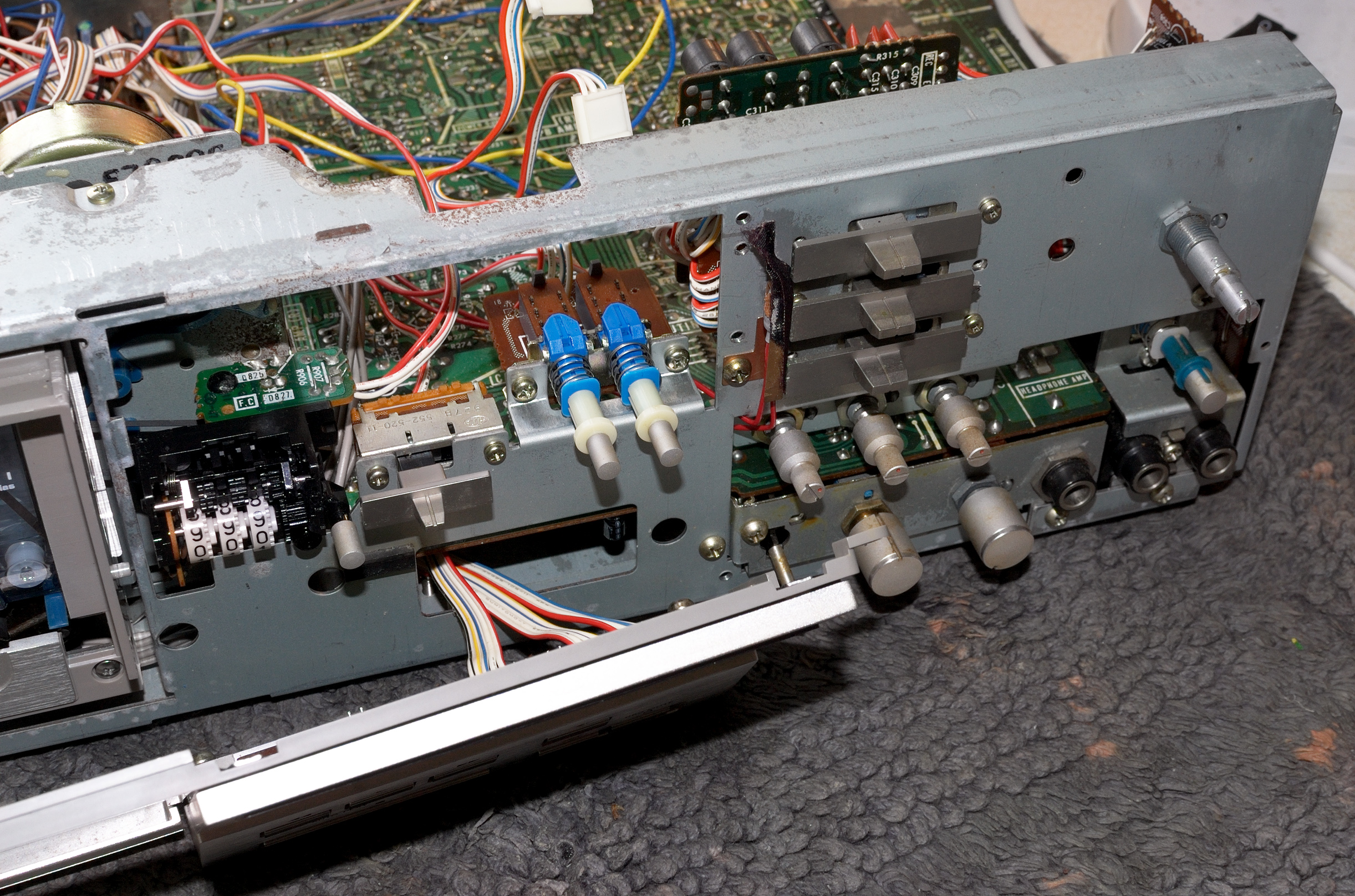
Work was be done on a soft surface
to avoid damages and scratches.
Here I've used an old clean carpet mat.


Main Audio Board.
Also, the mains transformer area is highlighted,
and adjacent pre-emphasis circuit.
(See comment below)

Warning: while the electronic design is very good, the audio board layout is poor in my opinion - too many components in such a small area made de-soldering difficult. Sanyo obviously just wanted these units sold!

It is recommended that anyone undertaking such work must use an efficient and accurate de-soldering gun/station.

Azimuth and playback levels were also calibrated from ABEX/TEAC full track reference tapes. Track height was not investigated, the new and old heads appear to have the same base thickness? Recording and playback to and from other third party machines was satisfactory - no obvious azimuth issues or instabilities.

Tape Type Provisions

The RD 4800 appears to have no provision for high bias tapes, like that of a typical Type II tape. Switching in 'CrO2' on the deck only alters pre-emphasis and de-emphasis; it does not increase bias.

No further testing has yet been done on any 'CrO2' or Type II tape.

Other Refinements Pending -

(1) Extra Transformer Shielding. 

Stray 50Hz electromagnetic fields appear to be picked up in the right channel of the recording circuit (but not playback), and I suspect probably during pre-emphasis, as this section is adjacent to the transformer as indicated above.

Observing Fast Fourier Transform plots on the playback noise (tape hiss) the interference is low, it mainly consists of odd-numbered harmonics of 50Hz (ie, 150Hz, 250Hz, 350Hz), but can be heard during very quiet passages.


(2) Higher than expect bass distortion - @50Hz, at 0VU record/playback, THD ~ 3%.

(3) New VU Meter Lighting.

(4) Pre-emphasis tweaking, otherwise known as 'Record EQ'.

Currently, the 'Standard' setting sets more pre-emphasis (ie, high frequency 'lift' above 400Hz) than the 'Low Noise' tape setting - this is not necessarily incorrect.

It is interesting when studying the circuit diagrams to see Sanyo allowing tweaking of pre-emphasis via ferrite cored inductor trimmers and one trimmer resistor for the 'Standard' tape setting.

With the new head in circuit, there is a high frequency rise of about 2dB/3dB starting above 10Khz which drops back to 1,000Hz levels at 15,000Hz.

Fall off after 15,000hz is rapid due to the limitations of the head, tape, tape speed, and restrictions applied from the FM multiplex filter. This rise may be 'smoothed out' if the pre-emphasis 'reasonant' frequency was moved to a higher point, and the associated in-series resistor increased to 'dampen' the Q-factor?

In the circuit below, ferrite core inductor trimmers L102/L103/L104 are adjustable and will alter the resonant frequency of the respective 'series' circuit. Capacitors too can be altered to change the 'resonant' frequency; circuit not yet tested).


From memory, the original Sanyo head returned similar frequency response results.

(4) Peak Level Lighting

Peak levels are often set at around +5dB to +6dB above 0VU, but in the case of this Sanyo, we have a sitiation where the response of a peak is slow, due the nature of the filament lamp. A better solution would be to employ an LED circuit, which is visibly faster acting.

Currently peak indication is set to 0VU, from which I estimate the actual peak is somewhere around +6dB above 0VU. This seems to be a sensible setting for this machine.

Summary

So here is the Sanyo RD 4600 after 35-40 hours work on it, and returned back to its case.

A very classy looking retro deck! However, there is more work to do on this machine.


These photographs were taken
using long exposure photography.

Refinements: Frequency Response

So back to some of the pending issues, we begin with record-playback frequency response.

With regard to tweaking the pre-emphasis as mentioned above, I increased the value of R319/R419 from 100 ohms to 150 ohms in an attempt to 'dampen' the peak rise above 10Khz. This has partially worked, and after reducing the bias a little, a quick and rather convenient assessment of the Sanyo record-playback frequency response was sought employing FFT on the application of White Noise at approximately -20dB, reference 0VU. The FFT plot is not ideal, but gives a good indication of the ability of the Sanyo.


Taking 1,000Hz as reference, there is deviation of -1dB at 10Khz, which then rises to about +2dB before settling back to 15,500Hz at -3dB. On the bass side, we see that at about 35Hz/36Hz, there is a -3dB drop.

A further reduction bias would raise the 10Khz level a little more, but I ran out of potentiometer resistance!

The electromagnetic interference discussed earlier is noticeable at this -20dB plot, in particular the dominant 150hz peak mainly in the right channel illustrated in red. A noise artefact at 20Hz also appears, quite where this comes from I do not know, but possibly from the brushless DC motor?

Low Frequency Audio Distortion

An irritating, but not-so-obvious problem with the audio was the low-frequency audio distortion that I percieved during subjective listening tests. This manifested itself as 'muddy' sound.

Several ideas came to mind as to the potential sources of this unwanted sound artefact. They were - (a) improper PB pre-amplifier biasing, (b) faulty muting transistors, (c) the record-playback multiswitch, or (d) the record head.

My first attack was to eliminate (c), the record-playback multiswitch. I knew this was going to be a risk when attempting to resolve the issue.

This 26-holed switch was very carefully de-soldered using a suction-based de-soldering station, and then removed from the board. The circuit board was then cleaned, but the job of opening up the switches (L-ch and R-ch) was a little intimidating - they are so easy to break.

With thoughtful and careful application, the job of cleaning or re-newing these two switches was done.


Record-Playback Switches After Removal from Circuit Board.


Disassembled Record-PB Multiswitch


Contacts Cleaned in Vice.


Before Re-assembly, then
Returning the Switches
to the Audio Board
 

Cleaned Audio Board


Multiswitches for Left and Right Channel -
Resoldered into Audio Board.
Full circuit board clean was done later.

Some 3 hours of work went into the job, but the improvement was only slight.

Next on the list of possible sources of the 'muddy sound' were the muting transistors

Labelled as Q114/Q214 on the schematic, these were initially replaced by 2SC2001. The thought had crossed my mind that I may have inserted the said transistors incorrectly?, but not according to the board layout as described in the service manual. Nor did I doubt the 'pinout' schematic for the 2SC2001 NPN transistors.

With the muting transistors removed, I went throught the process again of testing the sound.

Result? - postive!, no more muddy bass sound, no more mild mid-range 'stress' and treble came to life!


Distorton Figures


Tape: TDK C-46

Again, returning to the spectrum FFT plots, distortion at record/playback at Dolby level was re-estimated.

Third Harmonic Distortion is commonly defined by ...


At 100Hz at Dolby Level


Only two harmonics of the fundermental in question were taken, since the affects of remaining spectra are negligible. The relative differences  of the harmonics were estimated using FFT analysis.


At 1000Hz at Dolby Level


Leaking Transformer Interference

So far, a lot of work has gone into restoring the RD 4600, and although the mild right channel 'hum' (150Hz third harmonic) is a subject to be addressed, essential work on this deck is considered to be finished, at least as far as this blogger article is concerned. If and when additional shielding around the transformer is complete, this will be updated below. (03/09/2024)

Brushless DC Motor Assessment

After finishing returning the filament lamps to the VU meters, the brushless dc motor was examined. Of interest to the reader, here are some photographs.


The Brushless DC Motor


Pre-Emphasis Changes to 'Standard' Tapes

In the pre-emphasis or Record-EQ circuit, the 'Standard' setting is now configured so that it is now electrically the same as the 'Low Noise' setting internally. 

Previously the 'Standard' tape pre-emphasis was much greater than the 'Low Noise' setting, which forced a much higher high frequency rise during record (pre-emphasis), thus returning an uneven frequency response. Overall frequency response is now much flatter, but not identical - the Low Noise setting still shows the an after-10Khz rise (see above), while the new 'Standard' setting shows a dip around 10Khz of about 0.5dB to 1dB. Both settings can still be 'tweaked' using the relevant ferrite cored trimmer inductors.

Power Supply Fusing

While the service manual suggests in its schematic a full set of secondary fuses to protect the deck, there were no fuses to be found in this UK model!?


A suitable solution will be found later.

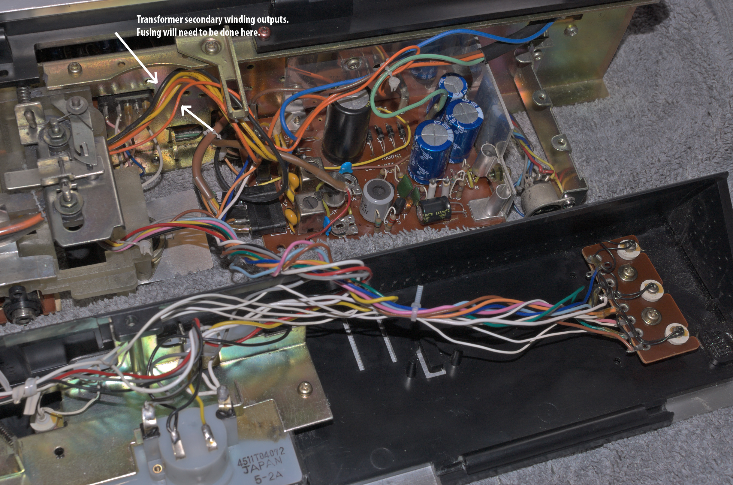
Secondary Transformer Cables.
No fuses found on this machine!


Fuse Solution


Three 20mm fuses holders were later inserted into the power supply circuit. These holders were placed electrically into the secondary side of the transformer.


Later I realised that the middle '800mA' fuse holder was not required, I had made a mistake, so the fuse was removed and the line reconnected within.


AC Transformer Secondary Winding Fuses -

2000mA Orange:
In line fuse for the unregulated DC power supply for the DC motor, and relays.
800mA Yellow: In line fuse for the regulated
DC power supply for the audio.

The fuse holders were later tied, and 'tidied up'.

Calibration Labelling


cassettedeckman@gmail.com

(Note: The Blogger editor is full of bugs, and so making editing very difficult at times. For this reason you may see the occasional unusual formatting.)

This article is in principle - finished, but small additions and corrections are still possible. (15/09/2024)

Friday, 10 May 2024

Sony TC-K75/TC-K81 Cassette Deck

Sony TC-K75 Cassette Deck

I bought this and received today as faulty - 'spares or repairs' quite cheaply off ebay.

 
Original Advert.


Rust and Corrosion at the Rear.

Heads and Pinch Rollers

Lots of issues, those currently known -

(1) The original switch arcing suppression capacitors had failed, these have been replaced.

(2) PSU has also failed? (reasons unknown),

(3) Capstan Motor plastic supports have broken, currently repairing them.


Cracked RIFA Arc Suppression Capacitors.
Replaced with 0.1uF + 120Ω snubber circuit.


Motor Supports: Had broken and now currently 'curing'.
Glue: 'Gorilla Glue'. 


The Condition of the Heads

These are Sony 'Ferrite & Ferrite' Heads.
Condition is very good.


10th May 2024.

______________________________________________


PSU Fault Detected  (11th May 2024)

From the electrically unsafe way the motor servo circuit board was situated at the rear of the transport, and the fact that the plastic motor support were broken, I sensed that the PSU had to deal with a short-circuit; possibly from a previous repair attempt, or from the breakage of the motor and servo supports?

With the TC-K75 deck switched ON, only the 5v rail appeared to be partially functioning?, while the 10v regulated rail was offering only 2.3v DC; clearly something was wrong.

Studying the circuit diagram reveals a number of fusible resistors which are employed as an alternative to fuses, combined with a convenient 'pull down' resistor. And sure, one such fusible resistor had blown - the R802!


A temporary solution to this was to 'wire in' a 20mm fuse holder with 200mA quick blow fuse. It worked, the 10v and 5v supply rails now work and the TC-K75 was brought back to life!

My initial fear was that the fault affected the main microprocessor - the NEC uPD547C, however this was not the case.


As a check, the DC current was monitored at about 67mA during PLAY mode - this is approximately the same current for many DC motors found on cassette decks.


As a precaution, the DC Motor Servo controller was electricaly isolated from the chasis, which I believe caused the initial short circuit!?

With the cassette deck now working - in Play/RW/FF and Record modes, I initially assessed the machine for basic overall functionality.


Auto Stop Failure

Later on, the TC-K75 had developed another fault - autostop was initiating for all modes. It transpired that either the infrared emitting LED or the infrared photo transistor had failed. New IR LEDs and IR photo transistors are currently on order - a temporary fix was put into place to confirm diagnosis.


The temporary fix was hoped to be a 'permanent fix', but since workable space and electrical isolation was not ideal, it became difficult to use the above configuration with confidence. Unfortunately, the IR light interrupter now also 'brushes' the phototransistor as it rotates.

Transport Rear Side

While waiting for the new LED/photo transistors to arrive, the flywheel back plate support was also strengthened using Gorilla Glue.


As extra caution, the motor servo circuit was further electrically isolated; solder side.


Later a quick test revealed that the motor is working well, as is the servo's ability to control motor speed. Wow and flutter figures were hovering somewhere between 0.03XX% and 0.04XX%, even with old pinch rollers and the original and old drives belts - I was very pleased!

Autostop Circuit Update (15/05/2024)

The IR LED and phototransistor order arrived today, so I began to work on the autostop circuit with components that made a better fit.

The Vishay TEKT5400S 'side view' IR phototransistor collector-emitter configuration suited the layout on this circuit board, but the Vishay BPV23F did not. I had to return a temporary IR LED to the circuit, which wasn't a problem.


The autostop works flawlessly.


Power Supply Unit

Although no problems have yet surfaced, the next task will be to re-cap, and possibly re-transistorise this unit. 


Sony CX174-1 Dolby IC Failure (20/05/204)

A few days ago, and after re-capping the PSU then later experimenting with coarse bias control at C154 and C254, the ability to record in the R-ch soon disappeared!?

After careful diagnosis it appeared that the front end of the CX174 IC had failed where the record head amplifier is situated. Readings of a DC voltage around -10v could be read at pins 14, 15, and 16.

This high gain voltage amplifier is seemingly configured in voltage-series feedback. The thought crossed my mind that I could 'piggy back' an external Operational Amplifier into the said circuit as a way to circumvent the problem.

According to the service manual the DC operating voltages at the non-inverting, inverting input, and output of the high gain amp of the CX174 should be '0v'. By '0v', I assume the service manual means a few millivolts or zero itself? Since the amplifier is ac-coupled only, then it should not matter?


A 'new' Sony CX174 Dolby IC has been ordered, and so while I wait, experimenting by inserting an external op-amp was anticipiated with interest.

The proposal was to alter the circuit as shown -


As I only have some LM741 and TL071 op-amps in stock, I could only use these.

The original pins of the CX174 were cut, and later on stripboard an 8-pin DIL socket was to act as the holder for the temporary fix.


Both the LM741 and the TL071 proved to be successful - recording can now be made in the R-Ch which appear to be just as good as they were earlier!

The one small caveat that surfaced, was the stripboard itself - for some reason the board is slightly conductable with a resistance across the board of over 500KΩ!? This dispite applying a insulation coating on both sides.

After the cassette deck had been on for 10mins or more, dc offset voltages at V+, V-, and Vout with respect to Ground begun to half their initial values. Offsets of around -19mV to -25mV for V+ and V-, and near zero for Vout were measured after about 15 minutes.

The DC offsets do not affect the AC performance of the amplifier, and there is normally provision on the op-amps themselves to 'null' this out.

Cross checking other CX174 ICs on this TC-K75 deck, and another external TC-K61 cassette player suggested that these offsets are normal.

Although this 'fix' works well, it is hoped that a 'new' CX174 IC will replace the original.

Under Biasing

One fact that struck me was that there appeared to be a degree of under-biasing for all tapes except Metal. Although this can be compensated for by switching to an appropriare higher bias switching, it is clear that this needs to be corrected.

The bias oscillator runs off a regulated '±9.4v' dc power supply which is separate from the main PSU. Indeed, control of the ac bias voltage oscillator (as supplied to the record and erase heads) is made via a dc potential divider network which then controls another voltage regulating transistor Q510 supplying the oscillator with controllable variable dc voltage. Measurements show that the regulated supply is -10.1v and 9.95v, which is good symmetrically.

However, the TC-K75's bias setting is not 'sitting' at the factory settings - Type I tapes are currently better served when the setting is for High Bias tapes!?

After much analysis, and some trial and error, the most productive solution was to remove the coarse bias capacitance trimmers C154/C254 and replace them with another set I had in stock. There wasn't anything particularly faulty with the previous setup, merely that turning the trimmers to achieve a maximum capacitance of 120pF was quite difficult. I'll look at these later.

Old C154/C254 Trimmer Capacitors Removed.
New ALPS Trimmer ready to be soldered in.

Before desoldering the current faulty Dolby CX174-1 IC and my 'piggy back' op-amp solution, the 'new' bias capacitance trimmer was tested. An additional 22pF was added in parallel per channel, yielding the higher bias required for normal operation of this deck.

An extra 22pF is added to the 20pF .. 120pF
offered by the C154/C254 trimmers.

Note: When adjusting the trimmer, care
must be taken - all screwdrivers must be
electrically insulated.


Why does Adding More Capacitance Work?

Adding more capacitance C, lowers capacitive reactance (or effective impedance) to the voltage bias frequency, allowing more ac bias current to flow from the oscillator to the record head.

Sony CX174-2 Dolby IC

De-soldering any IC can be a tricky process, and unfortunartely a little 'track lifting' occured, although hardly worth mentioning.

The 'new' CX174-2 was fixed into place using a 16-pin DIL socket; I wasn't going to 'chance' soldering an expensive IC.


Some small fixes and refinements are pending.

Tape Creasing Issue & Solution

Occassionally during Play I could hear and see tape being creased as it moved from one capstan to the next. The resulting audio would fade in the right channel and then reappear.

This was resolved at the end of the restoration project - the creasing or 'pinching' would crease the tape but only with some tapes, not all.

The problem appears to have solved by replacing the back tension felt pad with a fresh pad - no more tape creasing! 

Meter Display Failure

The MSL9351 LED meter display driver IC failed, quite possibly as a result of a short circuit as I returned the cassette transport back to the chasis. The failure didn't occur immediately, but some time later, so I cannot be certain. The problem with these decks is that - they were never designed with 'servicing' in mind, everything is so cramped.

Diagnosing the fault led me to checking the logarithmic amplifier (for the meter display), and the half-wave rectifier (which yields a DC 'record level') for the LED meter display unit. All indications were pointing towards the LED driver IC - the MSL9351.

Luckily I had a spare MSL9351 display IC in a 'parts machine'; the TC-K44.

Just previously, I replaced all LED driving PNP 2SA952 transistors with OnSemi KSA1015-GR and one 2SC1364 with a C1815-GR P33. Both replacements were all I had in stock as a direct replacement, both should be good for a short while, even though their maximum collector current ratings are just 150mA each. I will later change the KSA1015-GR for KSA1013 or perhaps a BC327-40 PNP, or similar when I have them in stock.

Studying the circuit revealed that each PNP driver transistor sources current for between 1 and 8 LEDs. A crude calculation of the LED's current demands is as follows: Id ≅ { (5v-0.25v) - 2.6v - Vdiode }/68Ω. If Vdiode(ON) ~ 1v (it's probably more), then we can expect that each diode will demand about 17.6mA, although I'm more inclinded to think Id will be about 5mA .. 10mA from experience, as these LEDs are not bright. Incidentally, if Vdiode(ON) ~ 2v, then Id ~ 3mA?


Assuming a worse case scenario where 17.6mA is the highest current demand for each LED, and then multiply this by 8 'ON' LEDs, then collector current for either Q603/Q604/Q605/Q606 is approximately 8 x
17.6mA or 141mA.


Original Sony MLS 9351 failure


Desoldering Stage


'New' MSL 9351 soldered in.
Conformal coating applied.


Fascia of TC-K75 minus LED Meter


Display Unit Returned
(prior to re-connection)
Original shielding plate has been removed.


Result? - success, the display meter now works! The cassette deck is now up and running. However, before proceeding, I shall wait for my new LED driver PNP transistors which have a Ic rating of 800mA/1000mA.

Currently on order: BC-327-40 PNP, and BC-337-25 NPN transistors.


New Meter Display Transistors (30/05/2024)

The said board has now been populated with PNP BC327-40 transistors - note the pinout is different from the original 2SA952.


Dolby Right Channel Error in Playback Mode

It is now apparent that the Dolby IC CX174-1 isn't working properly in the right channel. At first I wasn't sure if the CX174-1 had failed in this area, but all checks have lead me to this conclusion - replacing all capacitors and re-checking all resistor values around the CX174-1 did not change anything.

Two seperate R-ch/L-ch CX174s are involved in recording. Recording with the Dolby encoder on appears functionally correct since this has been verified by playback on other cassette decks. Indeed, an additional check of recording monophonic white noise at a low level (≅-20dB) and then checking playback (with Dolby OFF) does raise and lower the said white noise especially at high frequencies in monophonic form.

Another Sony CX174 IC will be on order soon, but in the mean time both left and right channel playback CX174 ICs have been de-soldered, and temporarily replaced with two 16 pin DIL sockets. The purpose of this is to identify which of the two ICs is definitely faultly, and allow for easier extraction and reinstatement of the said ICs.


I originally thought the left channel was faulty, with additional indication of a spurious offset DC voltage at Pin 13 appeared at approximately -22mV. This is not present on the other right-channel CX174, only some -1.3mV. More importantly this difference in offset doesn't appear to affect anything?


Once the 'new' CX174-2 arrived I opened up the deck and incorrectly put the new IC in the left channel socket, but it wasn't the left channel that was faulty - it was the right channel! Leaving the 'new' CX174-2 in place I swapped the two 'old' CX174-1 chips and very carefully returned the working IC to the right channel socket.
Dolby decoding is now fully working!


New Pinch Rollers
 
Although tape travel was good, I still wasn't 100% confident that tape crease would not occur, especially for thin tapes like that typically found in C120s.
 
In this example of the TC-K75, evidentally the take-up reel table was exerting (too?) much torque for the pinch rollers to deal with. Although difficult to prove, there seems to have been a measure of micro-slip randomly occuring. This sometimes resulted in thinner tapes being incrementally pulled through especially on one side. The result of which was that the tape began to 'run' sideways, ie running up and down the supply tape guide.

The take-up reel's torque is generated by a concealed brass driver turning a rubber idler, and this was possibly excessive - cleaning it made little difference. I decided to 'wet' the said idler with some silicone grease - this worked much better than anticipated. The reduction in torque was noted and the tendency of the transport to crease the tape almost vanished. However, replacing transport pinch rollers was still deemed necessary.


As with most cassette deck transports, fitting new pinch rollers is not easy - great care and patience is required.

For this TC-K75, the supply pinch roller is 11mm x 8mm x 2mm, and the take-up pinch roller is 13mm x 8mm x 2mm. Although on this occasion I have used a 13.5mm diameter roller so that capstan to pinch roller pressure is slightly increased. {Later revision: Sept 2024, I later returned a new 13mm pinch roller back to the take up side, no reason, other than it's the same size as the original}
 
Warning: a 13.5mm diameter roller may carry risks as the clearance between the roller and the roller holder is only 0.5mm. So I'm not recommending this roller to the reader - a 13mm diameter roller is the default (as found in this machine) and so assumed correct size.

Before continuing, an adjustment of the supply guide is required - the guide must be set so that the edges of the tape during PLAY do not touch the walls of the guide. It is a procedure involving some trial and error. Difficulty was further made as the cassette loader and holder had to be removed during alignment.

If I have one criticism of this transport it is this - there is no provision to adjust capstan to pinch roller pressure, it is simply set by a tension spring.

Tape flow was later observed for any signs of the tape sheet wavering or slightly buckling as it entered the supply capstan/pinch roller compression line. All is good!

Fifteen Minute Wow & Flutter Testing

Source: ABEX 3.15Khz Full Track.


Fifteen Minute Speed Drift Test


Other Images


Testing the new pinch rollers on a 'test' C120 tape.

The TC-K75 is working very well.

12/07/2024.