I bought this and received today as faulty - 'spares or repairs' quite cheaply off ebay.
 |
| Original Advert. |
 |
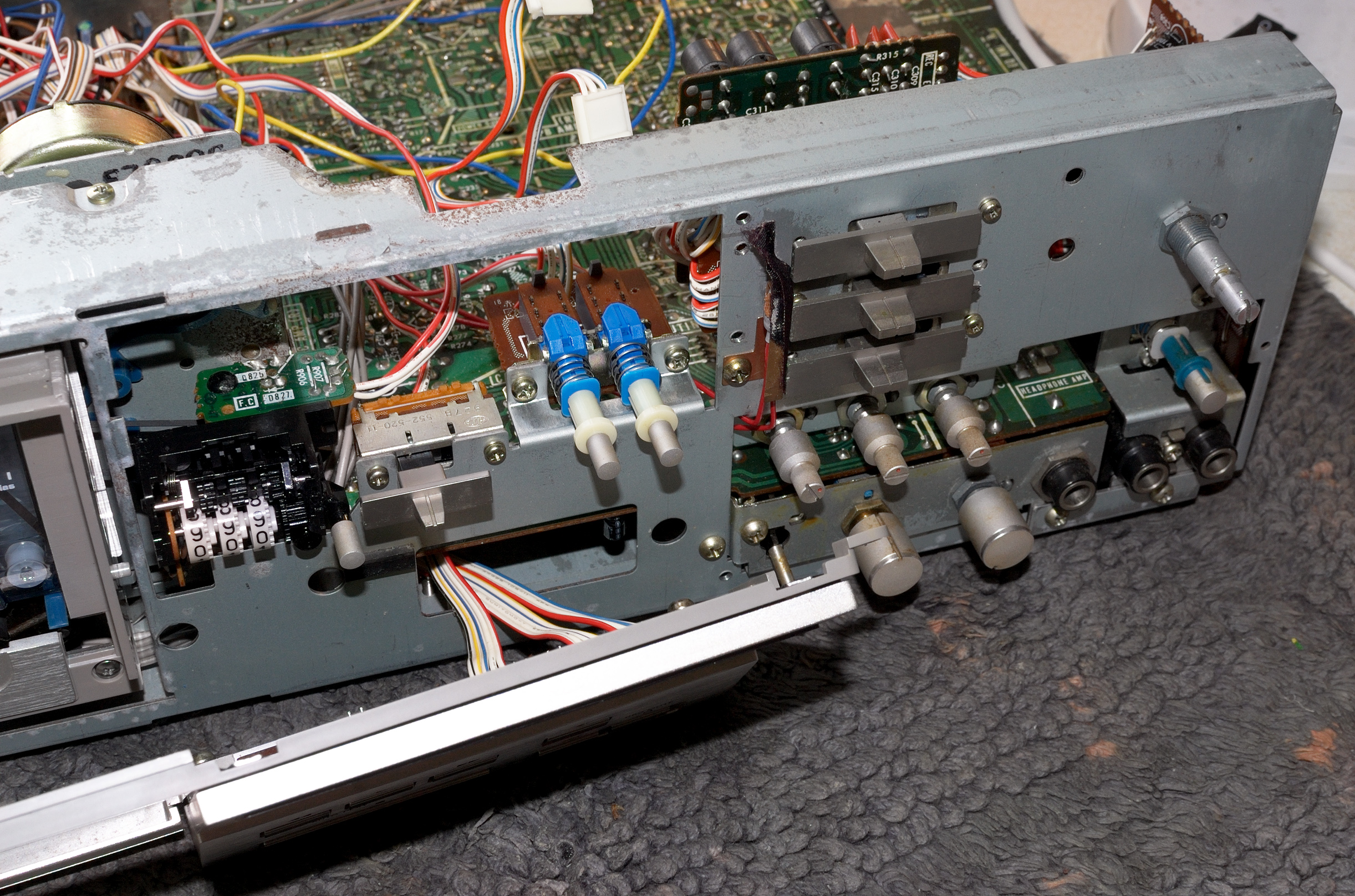
| Rust and Corrosion at the Rear. |
 |
| Heads and Pinch Rollers |
Lots of issues, those currently known -
(1) The original switch arcing suppression capacitors had failed, these have been replaced.
(2) PSU has also failed? (reasons unknown),
(3) Capstan Motor plastic supports have broken, currently repairing them.
 |
| Cracked RIFA Arc Suppression Capacitors. Replaced with 0.1uF + 120Ω snubber circuit.  |
 |
| Motor Supports: Had broken and now currently 'curing'. Glue: 'Gorilla Glue'. |
The Condition of the Heads
 |
| These are Sony 'Ferrite & Ferrite' Heads. Condition is very good. |
10th May 2024.
______________________________________________
PSU Fault Detected (11th May 2024)
From the electrically unsafe way the motor servo circuit board was situated at the rear of the transport, and the fact that the plastic motor support were broken, I sensed that the PSU had to deal with a short-circuit; possibly from a previous repair attempt, or from the breakage of the motor and servo supports?
With the TC-K75 deck switched ON, only the 5v rail appeared to be partially functioning?, while the 10v regulated rail was offering only 2.3v DC; clearly something was wrong.
Studying the circuit diagram reveals a number of fusible resistors which are employed as an alternative to fuses, combined with a convenient 'pull down' resistor. And sure, one such fusible resistor had blown - the R802!

A temporary solution to this was to 'wire in' a 20mm fuse holder with 200mA quick blow fuse. It worked, the 10v and 5v supply rails now work and the TC-K75 was brought back to life!
My initial fear was that the fault affected the main microprocessor - the NEC uPD547C, however this was not the case.

As a check, the DC current was monitored at about 67mA during PLAY mode - this is approximately the same current for many DC motors found on cassette decks.

As a precaution, the DC Motor Servo controller was electricaly isolated from the chasis, which I believe caused the initial short circuit!?
With the cassette deck now working - in Play/RW/FF and Record modes, I initially assessed the machine for basic overall functionality.
Auto Stop Failure
Later on, the TC-K75 had developed another fault - autostop was initiating for all modes. It transpired that either the infrared emitting LED or the infrared photo transistor had failed. New IR LEDs and IR photo transistors are currently on order - a temporary fix was put into place to confirm diagnosis.


The temporary fix was hoped to be a 'permanent fix', but since workable space and electrical isolation was not ideal, it became difficult to use the above configuration with confidence. Unfortunately, the IR light interrupter now also 'brushes' the phototransistor as it rotates.
Transport Rear Side
While waiting for the new LED/photo transistors to arrive, the flywheel back plate support was also strengthened using Gorilla Glue.
As extra caution, the motor servo circuit was further electrically isolated; solder side.
Later a quick test revealed that the motor is working well, as is the servo's ability to control motor speed. Wow and flutter figures were hovering somewhere between 0.03XX% and 0.04XX%, even with old pinch rollers and the original and old drives belts - I was very pleased!
Autostop Circuit Update (15/05/2024)
The IR LED and phototransistor order arrived today, so I began to work on the autostop circuit with components that made a better fit.
The Vishay TEKT5400S 'side view' IR phototransistor collector-emitter configuration suited the layout on this circuit board, but the Vishay BPV23F did not. I had to return a temporary IR LED to the circuit, which wasn't a problem.

The autostop works flawlessly.
Power Supply Unit
Although no problems have yet surfaced, the next task will be to re-cap, and possibly re-transistorise this unit.
Sony CX174-1 Dolby IC Failure (20/05/204)
A few days ago, and after re-capping the PSU then later experimenting with coarse bias control at C154 and C254, the ability to record in the R-ch soon disappeared!?
After careful diagnosis it appeared that the front end of the CX174 IC had failed where the record head amplifier is situated. Readings of a DC voltage around -10v could be read at pins 14, 15, and 16.
This high gain voltage amplifier is seemingly configured in voltage-series feedback. The thought crossed my mind that I could 'piggy back' an external Operational Amplifier into the said circuit as a way to circumvent the problem.
According to the service manual the DC operating voltages at the non-inverting, inverting input, and output of the high gain amp of the CX174 should be '0v'. By '0v', I assume the service manual means a few millivolts or zero itself? Since the amplifier is ac-coupled only, then it should not matter?

A 'new' Sony CX174 Dolby IC has been ordered, and so while I wait, experimenting by inserting an external op-amp was anticipiated with interest.
The proposal was to alter the circuit as shown -

As I only have some LM741 and TL071 op-amps in stock, I could only use these.
The original pins of the CX174 were cut, and later on stripboard an 8-pin DIL socket was to act as the holder for the temporary fix.


Both the LM741 and the TL071 proved to be successful - recording can now be made in the R-Ch which appear to be just as good as they were earlier!
The one small caveat that surfaced, was the stripboard itself - for some reason the board is slightly conductable with a resistance across the board of over 500KΩ!? This dispite applying a insulation coating on both sides.
After the cassette deck had been on for 10mins or more, dc offset voltages at V+, V-, and Vout with respect to Ground begun to half their initial values. Offsets of around -19mV to -25mV for V+ and V-, and near zero for Vout were measured after about 15 minutes.
The DC offsets do not affect the AC performance of the amplifier, and there is normally provision on the op-amps themselves to 'null' this out.
Cross checking other CX174 ICs on this TC-K75 deck, and another external TC-K61 cassette player suggested that these offsets are normal.
Although this 'fix' works well, it is hoped that a 'new' CX174 IC will replace the original.
Under Biasing
One fact that struck me was that there appeared to be a degree of under-biasing for all tapes except Metal. Although this can be compensated for by switching to an appropriare higher bias switching, it is clear that this needs to be corrected.
The bias oscillator runs off a regulated '±9.4v' dc power supply which is separate from the main PSU. Indeed, control of the ac bias voltage oscillator (as supplied to the record and erase heads) is made via a dc potential divider network which then controls another voltage regulating transistor Q510 supplying the oscillator with controllable variable dc voltage. Measurements show that the regulated supply is -10.1v and 9.95v, which is good symmetrically.
However, the TC-K75's bias setting is not 'sitting' at the factory settings - Type I tapes are currently better served when the setting is for High Bias tapes!?
After much analysis, and some trial and error, the most productive solution was to remove the coarse bias capacitance trimmers C154/C254 and replace them with another set I had in stock. There wasn't anything particularly faulty with the previous setup, merely that turning the trimmers to achieve a maximum capacitance of 120pF was quite difficult. I'll look at these later.
 |
| Old C154/C254 Trimmer Capacitors Removed. New ALPS Trimmer ready to be soldered in. |
Before
desoldering the current faulty Dolby CX174-1 IC and my 'piggy back' op-amp
solution, the 'new' bias capacitance trimmer was tested. An additional 22pF was added in parallel per channel, yielding
the higher bias required for normal operation of this deck.
 |
| An extra 22pF is added to the 20pF .. 120pF offered by the C154/C254 trimmers. Note: When adjusting the trimmer, care must be taken - all screwdrivers must be electrically insulated. |
Why does Adding More Capacitance Work?
Adding more capacitance C, lowers capacitive reactance (or effective impedance) to the voltage bias frequency, allowing more ac bias current to flow from the oscillator to the record head.
Sony CX174-2 Dolby IC
De-soldering any IC can be a tricky process, and unfortunartely a little 'track lifting' occured, although hardly worth mentioning.
The 'new' CX174-2 was fixed into place using a 16-pin DIL socket; I wasn't going to 'chance' soldering an expensive IC.

Some small fixes and refinements are pending.
Tape Creasing Issue & Solution
Occassionally during Play I could hear and see tape being creased as it moved from one capstan to the next. The resulting audio would fade in the right channel and then reappear.
This was resolved at the end of the restoration project - the creasing or 'pinching' would crease the tape but only with some tapes, not all.
The problem appears to have solved by replacing the back tension felt pad with a fresh pad - no more tape creasing!
Meter Display Failure
The MSL9351 LED meter display driver IC failed, quite possibly as a result of a short circuit as I returned the cassette transport back to the chasis. The failure didn't occur immediately, but some time later, so I cannot be certain. The problem with these decks is that - they were never designed with 'servicing' in mind, everything is so cramped.
Diagnosing the fault led me to checking the logarithmic amplifier (for the meter display), and the half-wave rectifier (which yields a DC 'record level') for the LED meter display unit. All indications were pointing towards the LED driver IC - the MSL9351.
Just previously, I replaced all LED driving PNP 2SA952 transistors with OnSemi KSA1015-GR and one 2SC1364 with a C1815-GR P33. Both replacements were all I had in stock as a direct replacement, both should be good for a short while, even though their maximum collector current ratings are just 150mA each. I will later change the KSA1015-GR for KSA1013 or perhaps a BC327-40 PNP, or similar when I have them in stock.
Studying the circuit revealed that each PNP driver transistor sources current for between 1 and 8 LEDs. A crude calculation of the LED's current demands is as follows: Id ≅ { (5v-0.25v) - 2.6v - Vdiode }/68Ω. If Vdiode(ON) ~ 1v (it's probably more), then we can expect that each diode will demand about 17.6mA, although I'm more inclinded to think Id will be about 5mA .. 10mA from experience, as these LEDs are not bright. Incidentally, if Vdiode(ON) ~ 2v, then Id ~ 3mA?

Assuming a worse case scenario where 17.6mA is the highest current demand for each LED, and then multiply this by 8 'ON' LEDs, then collector current for either Q603/Q604/Q605/Q606 is approximately 8 x 17.6mA or 141mA.


Conformal coating applied.

(prior to re-connection)
Original shielding plate has been removed.
Result? - success, the display meter now works! The cassette deck is now up and running. However, before proceeding, I shall wait for my new LED driver PNP transistors which have a Ic rating of 800mA/1000mA.
Currently on order: BC-327-40 PNP, and BC-337-25 NPN transistors.
The said board has now been populated with PNP BC327-40 transistors - note the pinout is different from the original 2SA952.
Dolby Right Channel Error in Playback Mode
It is now apparent that the Dolby IC CX174-1 isn't working properly in the right channel. At first I wasn't sure if the CX174-1 had failed in this area, but all checks have lead me to this conclusion - replacing all capacitors and re-checking all resistor values around the CX174-1 did not change anything.
Two seperate R-ch/L-ch CX174s are involved in recording. Recording with the Dolby encoder on appears functionally correct since this has been verified by playback on other cassette decks. Indeed, an additional check of recording monophonic white noise at a low level (≅-20dB) and then checking playback (with Dolby OFF) does raise and lower the said white noise especially at high frequencies in monophonic form.
Another Sony CX174 IC will be on order soon, but in the mean time both left and right channel playback CX174 ICs have been de-soldered, and temporarily replaced with two 16 pin DIL sockets. The purpose of this is to identify which of the two ICs is definitely faultly, and allow for easier extraction and reinstatement of the said ICs.

I originally thought the left channel was faulty, with additional indication of a spurious offset DC voltage at Pin 13 appeared at approximately -22mV. This is not present on the other right-channel CX174, only some -1.3mV. More importantly this difference in offset doesn't appear to affect anything?

Once the 'new' CX174-2 arrived I opened up the deck and incorrectly put the new IC in the left channel socket, but it wasn't the left channel that was faulty - it was the right channel! Leaving the 'new' CX174-2 in place I swapped the two 'old' CX174-1 chips and very carefully returned the working IC to the right channel socket. Dolby decoding is now fully working!

New Pinch Rollers
The take-up reel's torque is generated by a concealed brass driver turning a rubber idler, and this was possibly excessive - cleaning it made little difference. I decided to 'wet' the said idler with some silicone grease - this worked much better than anticipated. The reduction in torque was noted and the tendency of the transport to crease the tape almost vanished. However, replacing transport pinch rollers was still deemed necessary.


As with most cassette deck transports, fitting new pinch rollers is not easy - great care and patience is required.
For this TC-K75, the supply pinch roller is 11mm x 8mm x 2mm, and the take-up pinch roller is 13mm x 8mm x 2mm. Although on this occasion I have used a 13.5mm diameter roller so that capstan to pinch roller pressure is slightly increased. {Later revision: Sept 2024, I later returned a new 13mm pinch roller back to the take up side, no reason, other than it's the same size as the original}
Before continuing, an adjustment of the supply guide is required - the guide must be set so that the edges of the tape during PLAY do not touch the walls of the guide. It is a procedure involving some trial and error. Difficulty was further made as the cassette loader and holder had to be removed during alignment.
If I have one criticism of this transport it is this - there is no provision to adjust capstan to pinch roller pressure, it is simply set by a tension spring.
Tape flow was later observed for any signs of the tape sheet wavering or slightly buckling as it entered the supply capstan/pinch roller compression line. All is good!
Fifteen Minute Wow & Flutter Testing
Source: ABEX 3.15Khz Full Track.

Fifteen Minute Speed Drift Test

 |
 |
| Testing the new pinch rollers on a 'test' C120 tape. |
The TC-K75 is working very well.
12/07/2024.
Enjoyed reading your work on this machine. It gave me reassurance to tackle the tape travel problem my TC-K71 had. I could correct it for now by just cleaning the surface of both the idle tire and the felt pad (and their plastic wheels they make contact with).
ReplyDeleteAnother thing, concerning the electronics, I wondered you might have thought about. Would replacing capacitors in the signal path bring any benefit? Mine is a low hours, reliable working unit so caps (general purpose) are probably fine. I must admit I haven't studied the schematic so I'm not aware of the existance of an overal feedback loop, rendering this an unnecessary exercise.
Best regards and keep up the good work.
Most capacitors are okay, if anything I'd change the caps in the PSU, but otherwise they should be fine. Of interest, too much is made of capacitor 'ESR', when those commenting don't know much about it, and how it does affects the system in the mathematical context of the circuit.
DeleteSomewhere there's always a feedback loop for amplifiers, without it predicting gain would be subject to variations in hfe (current gain) which do occur. Negative feedback controls the amplification and stability which can be predicted accurately using mathematical analysis.
Cleaning idler tyres works, but only to a limit extent - I had to change the idler tyre for the take up spool on my TC-K61 a few years back.
Thanks for taking the trouble to write!
Was your take up reel's torque too high due to an issue with the magnetic clutch? If there isn't a washer inside that can lead to too much torque. I am having an issue where my torque is too low so i think the magnet in the clutch is too weak. I am thinking about removing the washer and using your idea of making the idler wet to see if that is a way around the issue.
ReplyDeleteOnce I finish a job and time moves on, I tent to forget the finer details, which is why I make a write up. Sorry, that I cannot help at this moment.
Delete