Thursday, 3 October 2019

Three Head Cassette Deck Phase Shifts


Three Head Cassette Deck Phase Shifts

Analysis
As my previous article suggested, there is a likeliness of phase shift between Left and Right channels from where the Record Head (RH) writes to the tape, to where the Playback Head (PH) reads the signal. 

At 10Khz, on my Nakamichi DR10 discrete 3-head deck, this was variable depending on the cassette tape used - on some tapes the phase shift was approximately zero, and on others approximately 90º. I could reduce this L/R phase shift to (effectively) zero even at 15,000Hz for a particular brand of tape, call this - Brand A set of tapes. But then would have to re-calibrate the record head RH azimuth for Brand B, Brand C etc . There were minute discrepancies at work here that I could not pinpoint, nor control.

I decided to perform a limited experiment with the Aiwa AD-F770 3-head deck, where the RH/PH heads are 'sandwiched' together. 

There is no independent control over either RH or PH heads here. Indeed, if there is some difference between the angle, or differential (L-to-L, R-to-R) distance of the two head gaps - that's it, I cannot change this!

Again, I decided to apply a test sine wave of 12,500Hz with a Maxell XLS-I tape inside.


As the trace shows, again there is a delay between left and right channels, perhaps some 60º?


Purely to satisfy my curiosity, I even altered the azimuth of the RH/PH during this experiment, just to confirm that no change should occur. Indeed there was no change in the delay angle.

According to my calculations, the physical delay between channels will have been in the region of 60/360*0.0475/12500 or 0.63um, ie just over 1/2 of a micron.


All very small indeed, and of course will not be noticed in speech or music recordings.

Whether these delays can be attributed to the tape warping/stretching between RH/PH heads, or a slight misalignment between the vertical left/right channel head gaps (effectively distances) is arguable - perhaps both?


At some point I realised that if this micro L/R delay distance 'D' is fixed by physical constraints, then ...
 
from basic physics we have,
 
v=f⨉λ   (velocity=frequency wavelength)
 
also, the delay distance D can be written ...
 
D= [φ/360]λ
 
and so substituting into v=f⨉λ, and rearranging we obtain ...

D = [v/360][φ/f]
 
where ...
  
v=0.0475m/s default tape speed, 
φ=phase shift, (degrees, not radians)
f = frequency of test signal.

If the above is true, then the ratio of φ/f will remain approximately constant, ie if you increase frequency f, then phase shift φ will increase also to match the constant ratio.
 
If that's a confusing concept for the reader (understandable), then I'll rearrange the formula and write ...
 
φ = D*f*360/v

So for my Aiwa AD-F770, we have ...


D=0.00000063 metres (from above calculation)
f=12,500 Hz (test signal)
v = 0.0475 m/s (for all cassette decks)

φ =  0.00000063 * 12500 * 360 /0.0475 = 60º. (as before!)

Predicting then, the phase shift for ...

10,000Hz .... 48º,
5,000Hz ... 24º,
1,000Hz ... 5º,
400Hz ...  2º.

Indeed, at 1000Hz, and below, the visible phase shift between left and right channels was difficult to discern on the oscilloscope. I've not bothered to photographed this.

Conclusion
So it appears that we cannot guarantee to make a precise (very narrow phase shift) azimuth tape from (any) three headed cassette deck? Simply because - we cannot trust the RH (Record Head) to effectively follow the azimuth line of the PH, even when we know the PH (playback head) is precise.

Perhaps the only precise and persistent (ie accurate) way to create azimuth tapes of our own - is to first correctly set up a two headed machine (Erase + Record Head) with one single full-width track record head, which is also the playback head. Of course such a machine must have excellent transport properties.

Exception: Today, I dug out the Revox B215. By chance, I put the machine through a similar limited experiment. At 6,300Hz input, the result was ~ 0º (zero!) L/R phase shift on play back, with just an occasional and slight differential wobble of about 10º. Wow, this machine is in a different league! (12/10/2019)

********************************************

3/10/2019: Articles are subject to the correction of mistakes, typo errors, and additions. 
Small amendment made on 25/04/2020 
25/8/2020 - partially rewritten article for clarity.

Tuesday, 1 October 2019

Creating your own Azimuth Tape?

Creating an Azimuth Tape
from a 
Full Track Master Azimuth Tape

Before I begin, I'll declare straight away that the processes and results of making your own azimuth tape from a 3-Head Nakamichi deck, is potentially flawed from the start. Although I cannot offer 100% guarantee of my claim, my findings suggest inherent problems in the creation of a precise azimuth tape of your own. So if you see one of these cheaply reproduced azimuth tapes on ebay, my advice is - think again!

My experiment with this idea began with checking the azimuth of my Nakamichi DR10 with an ant-audio.co.uk full-track reference tape. As it turned out, my Nakamichi DR10 and the said reference tape were identical (to within 0 - 22.5 degrees at 10Khz) as I checked the phase difference between Left and Right channels from the full track azimuth signal. 

Congratulations to both Nakamichi and ant-audio.co.uk! - I don't think their matching was down to pure chance, both parties know what they were and are doing!


The DR10 and other Nakamichi machines employ a sophisticated and highly engineered solution to aligning head tilt, track height, and azimuth for both record (RH), and playback (PH) heads independently. 

On the far right is a plastic (nylon?) slotted screw adjustment for PH azimuth, and to the far left - RH azimuth adjustment. Conventionally, on most other machines (inc the Revox machines), turning slotted screw heads allows alteration of all three alignment parameters. Of note, some force (although small) is needed to achieve these changes - not so with the DR10. The changes in azimuth require little force, and are indeed stepped in discrete increments so the engineer/technician can 'count' (if need be) how many discrete (clockwise/anti-clockwise) angle movements have been made - clever stuff!


Now that I knew that my Nakamichi DR10 playback head (PH) was (very probably) correctly azimuth aligned, the next step (as indicated in the service manuals) was to azimuth align the record head (RH) to the same 90 degree angle. This is achieved by injecting a 10Khz, 12Khz, or 15Khz  sinewave signal at any reasonable modulation (-20dB to -5dB, ref "0") into the record head, and observe the output (as seen by the PH head) on the oscilloscope. The theory is: observe the traces for maximum output, at which point both L/R channels should be in phase.


In the Nakamichi service manual, they do not mention phase alignment of both channels in this instance, but do instruct the engineer/technician to observe for maximum output

Why not mention phase alignment? The answer to this question came to me after several attempts to align the RH with the PH head. 

Sure, I could align these heads together perfectly - no problem, but, it wasn't until after checking the results with several different tapes that I realized that - every tape (Maxell, TDK, Sony, BASF/EMTEC etc) will probably yield a quantitatively different recording azimuth result!

Maxell XLS-1, or TDK CDing I
When I fed 12.5Khz into the RH for Maxell XLS-1, or TDK CDing I, I moved the azimuth for the RH for max output and perfect phase alignment - no problem!

L/R traces in phase (12.5Khz shown)

Then I experimented.....

SONY UX-Pro, TDK D (1988)
I put in these tapes, applied another 12.5Khz signal to the RH (record head).

The result - both the Sony UX-Pro and TDK D L/R output traces (based on the above (Maxell XLS-1/TDK CDing-I) RH alignment  settings) were not in phase! Wow, so what's going on?

L/R out-of-phase traces, 12.5Khz

Of course this can be corrected, if I altered the RH azimuth again to suit the Sony UX-Pro or the TDK D tapes.

Summary/Conclusion (so far)

Playback Head (PH) alignment is easy (using a full track professional alignment tape).

Record Head (RH) alignment may not yield a consistent result when mixing tapes - it seems to depend on the tape, and shell? The oscilloscope trace differences between RH and PH are small (45-90 degrees at 12,500Hz), but nevertheless measurable. I sense that Nakamichi and other manufacturers knew this too? 

No need to worry though, you and I won't hear these small high frequency phase shifts in music, but nevertheless I was surprised by the results.

What Causes this Azimuth Variability?
 
Well, I can only guess - the tape flow from Record Head (RH) to Playback Head (PH) is not perfect, there must be tiny stresses in the tape flow causing one channel to take longer to travel across than the other? 
 
31/3/2022: Also, there will be minute alignment
differences between left and right channels head
gaps in both heads?


Homemade Nakamichi Azimuth Tape 
Playback on Other 3-Head Cassette Decks

Now here is another oddity that I cannot explain -

(1) The Nakamichi DR10 Playback Head (PH) is aligned to that of the full track ant-audio.co.uk Reference Tape. Result: stable, in phase, and maximum output achieve - great!

(2) Then I record a 10Khz test tone at any reasonable level (-20dB, -10dB .. -5dB) and then align the Record Head (RH) so that Playback Head (PH) plays back the 10Khz signal in phase and maximum level - great, no problem there!

The theory - the DR10's RH is now aligned to both the PH of the Nak DR10, and the azimuth of the full track Reference Tape.

This means I can effectively use this new tape 'copy' as an azimuth tape for my Nakamichi DR10, BUT not for other machines!? - their playback traces have shown phase shifts in the region of  60-90 degrees!? Why ... I do not know!? Despite these other machines having already been PH-azimuth-aligned via my ant-audio.co.uk Full Track Reference Tape.
___________________________________________________

I've been thinking about this - again, it must be uneven micro stresses between L/R channels from the record head (RH) on their way to the playback head (PH) is going to produce this variability. 

The tape may be stressed more on one side than the other, thus taking a longer time to travel.  Surely then, we can never be certain that the RH azimuth is ever aligned to the PH azimuth?  Small discrepancies of around 45/60/90 degrees of L/R phase shift are inevitable?

THE ONLY FAIL-SAFE WAY TO PRODUCE A TRUE AND RELIABLE AZIMUTH TAPE OF YOUR OWN IS TO SET UP AND ALIGNED AND STABLE TWO-HEADED CASSETTE DECK OR A STABLE FULL TRACK CASSETTE DECK?

 
Calculating phase delay distances:
 
The phase delay physical distance between the two peaks or indeed any similar part of the two sine waves can be calculated from using the following expression: 

v=f*λ
or
velocity=frequency*wavelength

This is a standard physics equation relating velocity, frequency, and wavelength

What we require is to first find the effective wavelength of the modulated sine wave on tape.  Transposition of formula gives ...
 
 λ=v/f
or
wavelength = velocity/frequency

The velocity of the tape is 0.0475 metres/second
The frequency of my test sine wave is 12,500 cycles/second.

Then the sine wave wavelength is ...

λ= 0.0475/12500 = 0.0000038 metres 
or
3.8μm 
(3.8 millionths of a metre)

However, the worst 'delay' between left and right channels was approximately 90 degrees or 90/360*3.8μm.
 
Therefore, the physical delay (or distance) 
between channels = 0.95μm
or for 45 degree phase shift = 0.475μm 

In plain speak, the delayed wave is 0.95/1000 or 0.475/1000 of a millimetre respectively.


(3/10/2019: This article is subject to the correction of mistakes, additions, or subtractions)
Latest changes/amendments: 12/10/2019 
Latest changes/amendments: 4/11/2019.
Small changes - 25/04/2020. 
Changes - 18th November 2020.
Minor correction: 24/01/2021. 

Sunday, 22 September 2019

AIWA AD-F770

AIWA AD-F770 Dual Capstan Cassette Deck


I've had this deck since about 1999/2000, but seldom used it. About 3 months ago, I decided to play the machine and after a short while realized that the playback speed and stability were not to standard.

Having replaced the belts, the problem of playback 'wow' effect was still problematic - I thought the issue would have been eliminated, but apparently not.

The default 12DC, 2400rpm, CCW (counter clockwise) motor was ageing so I decided to search the web for a replacement. To reduce a long story to a few sentences - I bought several Mabuchi (originally Japanese?) non-brushless motors. At this point it is worth mentioning that the said motors are available on the internet, but could these be Chinese copies, probably?

Rescuing the pulley from the original AIWA motor (spindle ~2mm), I eventually assembled the whole cassette transport together (difficult job) until success was achieved. The transport now runs fine, with the machine running at the correct speed, subject to less than 1% error.

Mabuchi replacement - notibly smaller than the AIWA original.


Both the new Mabuchi (Chinese copy?) and the original motor have voltage regulators inside, and so it would be quite feasible to repair the olden - perhaps another time?

Motor Speed Calibration
So, how did I achieve calibration?  As I don't have a frequency counter I had to resort to other ways. 

My only route for now was to use my ant-audio.co.uk Reference Tape with a recorded 3000Hz test tone. 


I rigged up the AIWA to playback the tape through the left channel of my amp, and through the right channel a digital reference 3000Hz tone. On playback I listened to both. The two sine waves effectively modulate one-another (ie multiply), and the result produces a beat frequency - the effects of which I can hear. In theory two beat frequencies are produced - the sum and the difference in frequency.

Adjusting the motor speed (via a pot at the motor rear) one can hear the low frequency beat effect speeding up or slowing down. Ideally, the beat frequency should be zero, but I managed to get it to around 1-3 Hz. That's an error of about 3/3000 or 0.1%. Not bad! However, as with motors of this kind, adjustment is very sensitive, and likely to oscillate about the set point within tens of seconds, but as long as the temporary drifts aren't excessive, it shouldn't be an issue. In contrast my Sony TC-K61 has superb speed stability combined with ease of precise adjustment.

Playback Level Calibration 
According to the service manual, playback level trimming is adjusted via SFR203 and SFR204 potentiometers.


My ant-audio.co.uk Reference Tape is modulated at 400Hz, Dolby Level, and after cleaning the pots (Servisol) I examined the traces on the oscilloscope. The service manual suggests 580mV from AIWA's calibration tapes - which I assumed were at Dolby Level too? The oscilloscope below now reads ~3.2 divisions x 500mV/per division = 1600mV peak-to-peak. This equates to a rms value of 0.7071x800mV ~ 566mV .... close enough, in fact < 2.5% error. 

The truth is - playback level at Line Out doesn't have to be very precise, ±5% should be sufficient?, as long as both Right and Left channels are identical to within small margins, say ±0.5db?


Left trace -top, Right trace - bottom.


Peak Meter Calibration

Now that the output was calibrated, what about the meters? - they must read DL at this point. Potentiometers SRF701, 702, and 703 were first cleaned and then adjusted from below DL, and then finally 'resting' and stable on DL.
 
February 2022: Note: adjusting the Left and Right channel meters can be a little tricky! 

(April 2025: Go to 'FL Meter Calibration' near the bottom of this long page.)


Record/Replay Head Azimuth
This I already adjusted a while back, but just to check again, I ran the ant-audio.co.uk Ref Tape through the machine and made any (minute) adjustments. Ideally, both left and right channel sine wave traces should line-up (in phase), and display a maximum amplitude or output.


Record Level Calibration
For a deck that supposedly can self calibrate bias, record levels (ie tape sensitivity), and equilization, I found it strange that I could tweak the internal record levels myself, or at least set the machine to reproduce the same output for the same input, ie 0VU in gives 0VU out, or Dolby Level in gives Dolby Level out after invoking the auto-calibration feature. But it seems this was necessary, as this machine was apparently putting too much record level on the left channel by about 2-3dB for Maxell UR tapes, and others.


There are two potentiometers to help the machine calibrate - they are SFR401, and SFR402 located as shown (bottom right half of the overall board) ...


Amendment (May 2021) ....


I finally got the F770 to record, and playback 400Hz/1000Hz sine waves to the same level, estimated to be within the region of 0.5dB/1dB, according to the meters. Interestingly, not all tapes were so compliant, which I suspect is down to tape flexibility, the tape pad, and a small amount of head wear! Fast dv/dt transients however, can be a law unto themselves; some +2dB above that recorded.


Much of the calibration work I have done on this deck has not been strickly in accordance with the manual - for one reason, I don't have AIWA's original reference tapes.
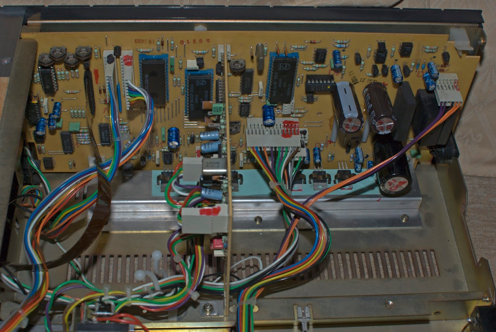

Power Supply
There's no doubt that this deck is a good machine, but its circuit layout is complex. The power supply was always getting warm, so I decided to clean the underside of the PS board, and replace three of the regulating electrolytic capacitors which take up less space. Hopefully ensuring better air flow than the previous configuration. 

A red marker labels the replaced capacitors.


*********************************


16/03/2021: 
 
Hello everyone,
 
This page gets more views than any of the other Blog pages, except for the Revox. 
 
So my question to you all is - why are you especially interested in this page for the AD-F770? What problems have you got?
 
I cannot help you individually, but your feedback would help me to identify common issues with the AD-F770.
 
Thanks.
 
************************************

Preparing the Aiwa AD-F770 for Sale
(March 2025)
 
Recapping the PSU
 
More new electrolytic capacitors replacing the old. 
 
Due to the congestion of components in the said area, some capacitors where re-situated on the solder side of the circuit board to aid better air flow, and keep the surrounding PSU temperature as low as possible.
 
New capacitors marked in red or green.


Servicing the Transport


Pinch rollers: Service pending. 
PLAY sliding platform: Service pending.

DC Motor/Servo Loading: So far with new belts in, the free-running dc motor/servo currents is approximately 75mA, and in PLAY mode (no tape) is approximately 81mA. These figures are a little higher than single capstan machines - that is to be expected.

Inner Belt Diameter: 76mm x 4mm
Outer (motor pulley) Belt Diameter: 82mm x 4mm 

Condition of the Erase/Record/Play Head:


Data Bias Circuit (08/04/2025)

Auto-bias calibration works for Type I, and Type II tapes, but has never worked for Type IV ('Metal') tapes. I've had the deck since 1998/1999, I knew of the fault before I bought the machine.

Chasing the fault is not an easy task, but there are suspect areas from circuit analysis that spring to mind.

Analysis of this circuit is lengthy and so I won't write about it, but on the data bias board there are a set of current sink ICs marked as M54514AP which could hold the key to this problem. 

They are employed to facilitate the digital-to-analogue converter, which sets the bias into a unity gain stage buffer OP Amp - IC501. Running the internal counter within the LA6505C IC through data states 00000 to 11111 sets this unity gain OP Amp to an increasing/decreasing voltage output directed to the bias circuit.


Today, the board had its ICs removed, and now I'm awaiting 'new' old-stock M54514AP ICs. Will new M54514AP work? Well, I won't know until I try it.

The M54515AP is a multichannel (7-bit) 'Sink Driver'. Basically, this is an array of output transistors in a 16 pin DIL package which provide two output states: open-circuit, or (near) close-circuit. 

The important parameter is the Vce(sat), ie the collector-emitter saturation voltage when the transistor is driven ON. For this design, it must be as low as possible. There are possible alternatives (ULN2003V12) - I may have to look at these later?

The board is also populated with 2SC2001-K NPN transistors which perform a similar task. I may indeed have to replaced some or all of tthese - I have plenty in stock.


Note the 16 pin DIL sockets ready for the 'new' current sink drivers.  


The Data Bias circuit was also re-capped, and as can be seen - the solder side looks good!

Now awaiting the 'new' M54514AP ... let's see what happens.

New Old Stock M54514AP

Well, frustratingly these did not work - all three 'NOS' M54514AP chips were dysfunctional, I even tested them 'offline'. These are 'simple' current sink drivers, basically a open-ended transistor collector circuit to which the user adds a 'pull up' resistor between +5v and the collector. Voltage input is applied at the base, being either (roughly) 0v and +5v.

Returning the original M54514AP ICs brought the AD-F770 back to life, and calibrating for Type I, and Type II was possible again, but still no auto-calibration for Metal tapes.

The seller of the 3 M54514AP drivers refunded me, and articulated that he didn't need me to return the drivers! Work that one out!

The 10 x 2SC2001-K NPN transistors on this board were also replaced with 'new' 2SC2001-K.

Successful Data Bias for Metal Tapes

Finally, successful biasing for Metal tapes was achieved, it may not have had anything to do with the possibility of a faulty Data Bias D/A circuit switching.

Note: As I don't have any other formal written references on this deck, I am forming an assumption based on the circuit diagram of the AD-F770, and my interpretation of it ...

It was found that the default setting bias for any tape was too low, and so Data Bias was unable to vary its bias level sufficiently for Metal tapes about these set points.

Re-setting Default Bias

Procedure - set a slow frequency sweep from 1Khz to 10Khz and set the record levels to about -20dB, reference 0VU. (38mV rms at line out)

In my case I used a 1990s TDK D60 cassette tape.

Turn SFR502 and SFR501 fully clockwise.

Turn the AD-F770 to 'monitor' mode and observe the 1Khz to 10Khz trace on an oscilloscope, then turn (right channel) SFR502 anti-clockwise slowly until both levels of 1Khz and 10Khz are equal. Note: Data Bias will use the right channel as a 'testing channel'.

Repeat the same for the left channel by using SFR501.

This will give you a standard bias 'marker' for your standard tape, in my case the TDK D60.

Test the deck's auto-calibration, Data Bias procedure will use your standard as a reference, and will alter the bias accordingly.


With this procedure finished, both Type II, and Type IV tapes should auto-calibrate without problems.

FL Meter Calibration

The service manual's description on calibrating the FL meters on the AD-F770 is a little ambiguous.

My interpretation is as follows ...


Take-up Pinch Roller Replacement (05/05/2025)

At least that was the intention.

I learnt that the roller is 13.5mm diameter, the steel pin is 2mm, but the width of the roller is 7mm. I only had 8mm in my stocks, so may be I'll order a new roller?


The shaft needed to be cleaned, it was quite 'sticky'.

Supply & Take-up Pinch Roller Mechanisms:

Both removed and cleaned - old grease was sticky. Cleaned with switch cleaner and cotton buds. Movement - much easier.


Revisted: DC Motor/Servo Loading 

So far with new belts in, the free-running dc motor/servo currents is approximately 45mA, and in PLAY mode (no tape) is approximately 54mA. Much better figures than earlier.

Inner Belt Diameter: 76mm x 5mm
Outer (motor pulley) Belt Diameter: 80mm x 5mm 

Mean Wow/Flutter: ~ 0.04x% to 0.05x% wrms.

SOLD. May 2025.
 
(Article is subject to corrections, alterations, and updates without notice.)
 

Saturday, 27 July 2019

Common Revox B215 Fault?

REVOX B215 REPAIR: Automatically stops after 2 seconds
 
Quite possibly the Rolls-Royce of all cassette decks, along with the likes of the Nakamichi Dragon, ZX9 etc. This machine had a very heavy price tag to match its design and build excellence. This particular deck of mine was internally dated: "May 1985".


ISSUE: The B215 would stop 2 seconds after any command to Record/Play/FF/RW, so what was happening here? As I initially searched the internet for answers, I discovered that this was not an uncommon problem. Co-incidentally, I found no online solution either, apart from the usual 're-cap' suggestions which, let's be honest - isn't going to work all the time. I was on my own to find a solution. 

Now it was time to find, download, and study the service manual preferably with circuits diagrams, then try to deduce the possible causes of this failure? 

Problem: Machine stops after 2 seconds of operation. Why?

Investigation: The first idea that came to mind was to examine the tacho signals which were generated from infrared LEDs modulating concealed photo transistors at the reel-motor side of the cassette transport.  

So how could I check this? Well, following the short ribbon transmission line ('Sensor Flex') from the cassette tape transport unit into the System Control Board, I was able to probe with an oscilloscope the integrity of the tacho data.  All four binary tacho signals were working fine as I forced the deck to Fast Forward.


With that confirmed, I then need to test the shape of the pulses at both input and output of the LM339N Quad Comparator. 

Examining the service manual circuit diagram, the LM339N is configured that it compares the tacho with a small reference voltage divider circuit (producing 2.5v), and will amplify to saturation (~5v) these 4 bits of data to the MAB 8440 Microcontroller if the tacho signal is greater than 2.5v. 

The result of this investigation? The LM339N was failing. Two out of the four output bits were in error, they were permanently 'high' or at 5v. 

Just some notes I made - wasn't initially intended for this blog.
 
Comparitor Circuit in More Detail


Apparent circuit showing just one data bit of the four.

How does the circuit work?
Each one of the photo transistors is activated by the infrared LEDs.

Two states exists: 
QP=on, the circuit to the left of the red line becomes 'live' at approximately +5v.  The V+ terminal input to the LM339N is also held 'high' (depends very approximately on the potential divider 5v*Δ47k/[2.2k+Δ47k] setting) and so the LM339N saturates and so Vo ~ +5v.
QP=off, and the circuit to the left of the red line becomes effectively an open-circuit or at least very high impedance. At this moment the V+ terminal is approximately grounded, and the V- terminal drives the OP Amp comparitor into an inverting state, in this situation we have Vo ~ 0v.

I actually measured the (non-inverting) V+ terminal voltage when the 47 K trimmer was set to about half way. During fast-forward operation (or RW or Play) it oscillated approximately between  0.1v and 4.9v. Varying the trimmer, I could force the V+ terminal input to zero - this would switch off any FF,RW, or Play action.


Back to the job of repair ...

Confident that this was at least one source of the problem I ordered some DIL sockets and a set of LM339N OP AMP chips.

As the original LM339N was soldered in, I had to be careful when desoldering. Of course I would have preferred if the chip was positioned via a DIL socket. The first and best approach to desoldering is NOT to desolder, but to cut the legs of the LM339N on the circuit board side only. A slow process, but one that works. After pulling the LM339N body away I proceeded to desolder or pull through the remaining legs. This way I can be almost sure that I won't over heat and lift the tracks - a nightmare scenario! The new DIL socket was soldered in, and the new LM339N positioned in place. 
(Amendment: Of course I could have desoldered using a copper braid or solder wick, which is very effective and probably better, but at that time I didn't have any in stock. 20/4/2020)


System Control Board, track side.


The top two DIL pins are redundant.
Careful soldering is a slow but rewarding process. I eventually and carefully returned the board to the B215. 

As a precaution, I previously colour-coded the cables so was confident that I wasn't going to make any silly mistakes in putting this machine together. The next step was to switch on!  


 The Revox B215 now works! 👍

 
Recently I demagnetized the heads and capstans and ran through a Dolby Level 400Hz reference tape at 200nWb/m field strength ANSI standard. The meters read "0", which appears to be in accordance with the service manual. So even after 34 years, this machine still retained its playback level calibration! 

Re-capping the boards is something I need to do, especially at the PSU stage, perhaps this autumn or winter? However, so far everything is working fine. 

Some additional pictures:

Frontside view of transport and the Sensor Ribbon.
 

27/7/2019 (Subject to changes and corrections)
Revised: 28/7/2019, 8/04/2020. 

System Control (Main Board)
All the electrolytic capacitors and voltage regulators (LM317/LM337 series) have been replaced. Two axial 2200uF 40v-rated capacitors have been replaced with 2200uF 50v-rated radial types, simply because I haven't got any axial capacitors presently in stock.
9/04/2020.


May 2020: New axial capacitors now in circuit.

Minor additions: 27/04/2020, May 2020, 2/08/2020. 12/11/2020.
14/12/2021, 17/10/2022.

Also see ... Playback Calibration


Readers: This blogger page of mine receives more attention than any other. Those who visit this page may have problems with their Revox B215, if so was it the same problem as mine? You can send a comment below - it would be interesting to know how people got on with their repair work.