LED Driver with Current Limiter
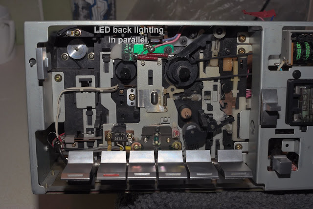
Recently my AKAI GX-M10 cassette deck's tape progress lighting failed. I noted that the filament had burnt out and so I contemplated with the notion of making my own, but this time the lighting was to be driven by a simple LED display.
Having arranged and soldered two 1.8mm LEDs in parallel, the next task was to design a circuit to run the LEDs at the recommended diode current of 20mA, at 3V.
Later, after observing that this was probably excessively bright, I then experimented by driving the LEDs with voltages varying from zero to 3v, and noting the brightness. It was then I realised that an ideal solution would be to have a current controller fitted to a LED circuit – thus this transistor based, LED driver circuit with adjustable current control was about to be analysed and tested.
Of course a much simpler LED arrangement in series with a suitable resistor would be sufficient, but the challenge of an alternative 'on line' controller for the LED's brightness was a plus-factor.
A standard current limiter circuit is shown below, together with my labelling of various (conventional) current equations, passive, and active components.
Brief Circuit Analysis
In a working circuit after switch on, the circuit stabilises with both T1 and T2 conducting, and importantly - the higher power transistor T1 controlling the current passing through both diodes entering the collector Ic1.
In a steady state condition - a potential difference is developed across Re, which according to ohm's law is virtually Ie*Re. This voltage Vbe2 (Ie*Re), if increased (via Re → Re+𝜟Re) also increases transistor T2 into further conduction - resulting in the collector-emitter Vce2 voltage of T2 to drop momentarily, thus increasing the current through Rb (a voltage drop), and thereby dropping the voltage at Vbe1. This transient Vbe1 drop then lowers the current Ic1 (and Id), and Ie1, and thus lowers Vbe2. This new Vbe2 voltage is then fed back into the loop again. The new decreased Vbe2 now increases Vce2, thus reducing the current through Rb, and increases Vbe1 again.
This is a feedback cycle that loops instantaneously until equilibrium current Ie1, Ic1, or Id is established.
There is another factor that also determines the driving voltage across the base-emitter of T1 - Vbe1. And that is the voltage developed across Re (approximately Re*Ie) which effectively adds Voltage Series negative feedback to the loop.
Hence, there are two influential factors in driving the Vbe1 voltage: the feedback loop containing T2, and the in-series voltage across Re, ie Re*Ie.
So which then will be the more dominant? - this will depend on the input current to T2 (Ib2), and the current gain (hFE2) of T2.
In summary then, with Re static, we observe that Ic1 is static, and then find that varying Re, ie Re → Re±𝜟Re allows us to control the feedback loop, and with this control Ic1, Id, and thus LED brightness.
Varying Re is the key to controlling LED brightness.
The accuracy of the expression is going to be dependant on the variables Rb, and 𝜷1 and 𝜷2 which vary depending on collector currents. T2's measured 𝜷2 was relatively static at around 𝜷2~10, while 𝜷1 was more dominant and variable depending on Ic1.
The circuit has been tested and fitted to the AKAI GX-M10 - 100% success!
 |
| The 'earth' (0v) side has been secured - the initial problem was finding an easy accessible 16.7v point which I eventually did. |
 |
This LED Driver with Current Limiter blog/article is periodically updated and corrected mainly due to mistakes, typo errors, blogspot.com editor bugs, and will be updated without notice.
| cassettedeckman@gmail.com | |||||||||||||


No comments:
Post a Comment