Wednesday, 6 November 2019

YAESU FRG 7700
Servicing, Discovery, & Issues


Basic Serving Objective
My initial task, was to service the receiver, and the first job was to replace all electrolytic capacitors on the top board. This was eventually achieved with no issues. As a matter of course, I also cleaned the post-soldering areas with isopropyl alcohol and an old tooth brush – its vital that no unintentional connections are made.

However, after replacing the KF2510 connectors I made a casual error – mistaking P17 for P24! The set worked initially for a short while, then one of the 10 ohm resistors began to heat up, something was obviously wrong! After studying the circuit and the circuit diagram, I replaced R248 (10 ohm ½ watt), and as a precaution both Q59 (C1384R NPN transistor), and D46 (10v zener diode). The set now worked fine.

FIP5A8B Display
The display is continuously updated from a single 7-segment (plus 1dp), 8-bit multiplexed data bus, were each digit value is allocated a quota of time. The 8-bit data is bused to the FIP5A8B unit from the MSM5524R microcontroller. Each digit within the FIP5A8B appears to be strobed or activated sequentially by Q52 to Q56 which are controlled by the MSM5524R.

Overall, the display works well, but I noted some years after I bought the FRG-7700 in 1981, that when in ‘DIM’ lit mode, all the display digits tended to leave the ‘c’ segment on the 7-segment display partially lit? This ‘c’ segment is the single segment which is vertical, on the bottom right. 


I originally suspected, and still do, that the MSM5524R Microcontroller has a minor fault somewhere within the workings of pin 29?, which is the 'c' segment in the a,b,c,e,d,e,f segment naming convention. 

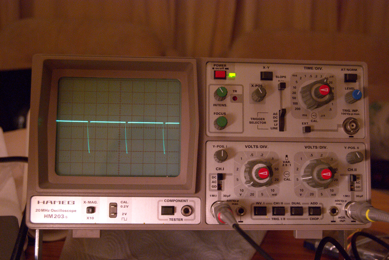
It is as if the output transistor stage is not effectively switching fully in the OFF state? Oscilloscope traces indicate residual noise, which is possibly and effectively leaving this partially ON?


Only recently did I learn that in ‘DIM’ mode, pins 25-31 (7-segment data), and 35 (decimal point) have their pulse-widths narrowed when busing the data from the MSM5524R to the FIP5A8B - the oscilloscope traces confirm this.

Voltages and traces for all 7-segment pins (inc 29) when ..
logic state = Segment ON.
No DIM mode.
Pulse at full width.
Centre line = 0V (Earth)
Voltages and traces for all 7-segment pins (not inc 29) when ..
logic state = Segment ON.
DIM mode.
Pulse at reduced width.
Centre line = 0V (Earth)

At the partially faulty Pin 29 'c' segment.
logic state = Segment ON
DIM mode 
Plus at reduced width, plus noise 'blip'.
Note also: reduced negative potential.
Centre line = 0V (Earth)
Voltages and traces for all 7-segment pins (not 29) when ..
logic state = Segment OFF.
No DIM mode.
Centre line = 0V (Earth)
Pin 29 
logic state = Segment OFF
(Full Brightness or DIM mode, the traces are almost identical)
(Note: lessened negative voltage and noise)
Centre line = 0V (Earth)
It is apparent that all 7-segment data pins behave well - when any segment is ON, or OFF (full brightness or in DIM mode), but pin 29 (the 'c' segment) does not - clearly problems within the MSM5524R!?

So far, and to eliminate other possible causes (although unlikely) and for the sake of completeness I replaced all 7-segment display-digit synchronising transistors Q52 to Q56, plus all small rectifying and signal diodes (1SS53) all involving working the Astable Mulivibrator (a DC-DC Convertor). They are the D47..D50, D51,D52, D55, D56, D42, and D43 replaced with a common, but reliable 1N4148 type. Both Q60 and Q61 switching transistors in the Astable Multivibrator circuit were also replaced.  

Relative Potential at input of FIP5A8B
Negative DC potentials (wrt Earth) are highlighted below, and later the oscilloscope traces at the 7-segment data bus input to the FIP5A8B.

User's Manual states the rectified DC-DC Converter should produce -25v supply, but it is producing approximately -35v.

Digit Strobe/Sync Signals to FIP5A8B
Shown below are just two (of the five traces) at the bases of transistors: Q52, and Q53 as they consecutively switch ON and OFF the respective digits on the FIP5A8B display. Unfortunately, I don't have the facility to display all 5 at the same time.
'Low' state at 0V switches ON these Q52/Q53 PNP transistors.
Note the switching frequency: Approximately a 3ms period in the 5-digit update cycle. The whole 5 digit display appears to be updated (repeated) in 3ms or at about 333Hz.

FIP5A8B Clock Generation
The Astable Mulitvibrator and buffer transformer (form a DC-DC Convertor) appear to be the FRG-7700's generator for the FIP5A8B display 'clock'. The voltage trace shown is effectively across the input of the FIP5A8B, it's only approximately 4 volts peak-to-peak.

The clock frequency is calculated from f=1/T, 
where T is the period of the waveform. 

Since T=150us, therefore f=6667Hz.


Compare: FIP5A8B clock (6667Khz) to
MSM5524R (333Hz) 5-digit-block strobe frequency.
20:1 ratio.

Pull-up Resistor Bank
I also lifted the old resistor bank RB01 (8x 100K ohm) and replaced this with my own resistor network. 


All new components are marked on the circuit diagram below.

Note: Pin 29 'c' segment,which didn't switch cleanly from +5v to - 34v.

Front Dial Display Lamp
Later, the front dial display lamp (PL4001, 12v 100mA?) was replaced with a ‘white’ 5mm LED, in series with 2 x 220 ohm 1/8 watt resistors – the DC source was measured at approximately 10.6 volts.

Calculation is relatively easy: The full brightness of the LED is quoted at about 20mA. Without drawing the circuit diagram, and writing out Kirchoff's Voltage Law, the maths does arrive at ... (10.6 - 3)v/(2*220 ohms), which is approx 17mA. Not 'full on' brightness, but bright enough, the diode should last longer too!

White LED glued into a washer.
White 3v LED, glued washer 'gromit' and glued into place. 

I later isolated the LED and contacts from any possible electrical shorting.  

Zener Diodes at Display Driver Stages
Not stopping with this servicing adventure, I decided to change the two zener diodes D53 (7.5v), and the D45 (5.6v). The D45 is involved in fixing the voltage to about 5.6v and allowing the MSM5524R to apply 5v and activate the sync transistors for the FIP5A8B display unit. 

However, to my shock after switch on, the display only indicated one digit, which was random every time I switched on. I knew immediately what was happening – the synchronising transistors were not able to update any synch pulses to the digit display - they were locked out by some biasing error? To my disbelief, almost all of the pack of ten ‘5.6v’ zener diodes I bought were faulty! I quickly resolved the issue (for now) by returning the original 5.6v zener to its place.

Weakened Solder Joints
Through repetitive, but careful disassembly and assembly, the pins that hold the KF2510 connectors began to fracture the solder under-board, but not lifting the tracks. So as a precaution , I flowed fresh solder around the joints and their strength returned.

Ideas for the Front End Tuner Section
I may at some point, replace the signal diodes 1SS53 with BAT42 Schottky diodes, which have a lower forward voltage – somewhere around 250-350mV.  Will these allow the set to become more sensitive, especially at 21Mhz and higher?

Front End Signal Diodes Replaced (30/11/2019)
Just for experimental reasons, I de-soldered the old 1SS53 signal diodes, and carefully soldered in, a new set of BAT42 Schottky signal diodes. The BAT42s have a lower forward voltage. My thinking was - a more sensitive Front End? Results so far are very positive!


3/12/2019: Just replaced the two zener diodes that serve the display: D45 (5.6v), and D53 (7.5v). I've used 1watt zener diodes for no ther reason than to make sure that neither break down.

Latest shot of the top board, FIP5A8B display side.

Currently, the FRG 7700M is working very well! 
The article may still be subject to corrections without notice. Latest amendment: 3/12/2019.

Saturday, 19 October 2019

SONY ST-SA3ES Attempted Repairs

I bought this Sony tuner back in 2005, although within 12 months the tuner was hinting that it had a fault - an intermittent albeit short noise burst, followed sometimes by loss of signal.


Since then I've tolerated the inconvenience, and even attempted to resolve the issue by replacing the multi-regulated power supply with a new voltage regulator chip. I thought the power supply was being erratic, but as it later turned out, this was not the source of the problem. Much later, desperate to find the cause, I examined the underside of the circuit board looking for short-circuits, and even cleaned the board with isopropyl alcohol and a tooth brush - but still the intermittent noise bursts and general loss of signal would randomly surface.

Added to this problem, one of the MPX LPF filters appeared to have shorted, so I had to electrically bi-pass this part of the circuit to get the set working again. Effectively, I believe one channel is multiplex filtered (eliminating the FM Stereo 19Khz pilot tone), while the other is not.

Already compounded with these problems, the frequency display also over-reads by +0.05Mhz.

Display should read: 90.50MHz
So to summarize, the issues are ..

(a) Intermittent noise bursts/signal losses (now random, but seemingly a simple connection issue?)
(b) Left channel output is now not multiplex filtered, ie 19Khz Pilot Tone 'leaks' through.
(c) Frequency display, in error by +0.05Mhz.

To date, I have replaced ...

(a) The Sanyo multi-voltage regulator in the power supply.
(b) Bi-passed MPX filter air-core transformer/choke. (To be re-installed once I find a replacement)
(c) Replaced some electrolytic capacitors on the main board.

What a mess!

Attempted Diagnosis of Sporadic Loss of Signal
The other day, I finally de-soldered the delicate Front End tuner section, hoping to find some indication of why the tuner delivers occasional sporadic noise bursts, and random loss of signal.

Thoughts were aimed towards (a) a faulty Phase Lock Loop (PLL) circuit?, (b) a simple loss of RF signal connection within the Front End Tuner section?


Top right in blue: the antenna A/B relay switch.


The idea of a noisy antenna A/B relay switch had crossed my mind, and so I took the ambitious step of opening the front end tuner, which also contains a heterodyne mixer, and a phase lock loop unit.


Nothing obviously at fault from above, I then de-soldered the said circuit and examined the underside.

I had a hunch that there is a problem with basic signal circuitry, so I mulled over the underside of the front-end unit. As illustrated above there are two FM antenna inputs, and the apparent common RF point to which either one of the antennas will be connected depending on the options on the display panel of the ST-SA3ES.

After some thoughts I made decision to short-circuit the common input RF point to antenna A, so that this antenna will always be 'on'. In this scenario, the antenna A/B relay is partially ineffective, although still physically active - the ST-SA3ES can still receive RF input from either: A and not B, or A and B.


After reassembling carefully, the tuner appears to be working without loss of signal, although I think I did detect one of those noise bursts which only last for a split second?

So far, and many hours later, the Sony ST-SA3ES tuner is working well, and is stable in operation. The other issues like the lack of a LPF LC circuit in the MPX section, and a display error of +0.05Mhz will have to wait until I find a solution for them.

Looks like this loss of signal is not an isolated incident, it is spoken of here .... https://forums.digitalspy.com/discussion/1791340/sony-narrow-band-tuner-same-problems-with-both

19/10/2019

21/10/2019: While the RF signal cut-out (much like unplugging the antenna) seems to have been stopped, the occasional low level rain-like noises (sometimes surface, as if there was a build up of charge which then finally discharges. These two faults could conceivably be two separate issues? The latter does sound like a chipset partially failing, perhaps the PLL unit?

24/10/2019: After deciding at one last go, I de-soldered the RF Front End again from the main board, and re-capped the Front End unit, except for one electrolyic capacitor. I decided to replace them so that I could at least identify which were the probable components of this rain-like (mono) noise that is experienced usually after switching on. The noise soon disappears after a few minutes, but may re-surface from time to time.


Desoldering this, and the capacitors from the unit was no easy job - the new capacitors have been marked in red.

I think I can confidently say that the source of the random rain-like noise can be sourced at the phase-lock-loop chip, or the circuit connection surounding it. Once the noise had gone, I can often make it return by pressing the chip with my finger - so it has to be the chip, or its immediate surrounds?


before re-capping, the LC72130 PLL - the source of the rain-like noise after switch on?
I won't be opening up the Front End again, the soldered connections are too vulnerable because of de-soldering wear and tear.

Sony recommends replacing the unit if problems occur, I can see why!

28/10/2019: The tuner to my surprise has now decided not to receive signals, identical in sound to pulling the antenna out. The front end is now effectively an open-circuit - all that work for nothing!

Time I think to scrap the ST-SA3ES completely?

6/11/2019: I have pulled the circuit board out, and will salvage some components from it. The Phase Lock Loop chip must be faulty? I don't think I shall bother to replace it, after all, I cannot be absolutely certain what the issue is. This type of fault has been recorded several times on the internet including a Russian website - no definitive solution found it seems anywhere? 
******************************************************

Friday, 11 October 2019

ABEX Azimuth Tape Specifications

This is just an academic exercise to pursue, let's see where it takes me ....


Reference tapes like ABEX quote azimuth errors of angular measure in degrees, minutes, and seconds, ie typically: 0º ±2' 0", 0º ±4' 0" etc.


Question: How will this translate into any L/R channel phase delay on the oscilloscope? What can I expect to see? 

I am going develop an expression where φ is a function of the quoted azimuth error. Remember, φ is the phase delay we see on the oscilloscope.


From earlier articles, the electrical (and physical tape) L/R channel delay D appears to be fixed, and is given by ...


Also, let's inspect this simplified cassette tape diagram below - one half only shown. The electrical/physical delay D in this context is relatively easy to compute since a right angled triangle has been formed.


From our knowledge of trigonometry we can see that the azimuth angle (anti-clockwise) from the 90 degree vertical is....


Where BC = cassette tape's centre-to-centre track distance, which is very approximately 0.9mm (ie, 9x10E-4 metres, SI units) Substituting D into the inverse tangent formula gives ...


The angle ACB is the quoted azimuth error/difference, but I want to find φ, a predicted oscilloscope phase shift trace. Rearranging the trig expression gives ...


At a typical 10,000Hz azimuth test frequency (f=10,000Hz), the ABEX quoted azimuth errors of their reference tapes were of the order ~ 0º ±2' 0", 0º ±4' 0". In decimal form this is 0.0333333°, and 0.0666666° respectively. (Note: I'm not using radian angular measure)

So then, the expected ABEX tape L/R channel phase error at 10,000Hz on the oscilloscope should be in the region of ... ±40º, and ±80º. Or in more practical terms approximately ±45º, and ±90º.

As ABEX and others cannot guarantee perhaps finer tolerances, I suppose the only way to get a near precise estimation of true azimuth would be to purchase a sizeable sample (say 6 or more?) of identical tapes, then devise a method that aims to achieve a median valuation from the set of acquired tapes?

(Articles are subject to the correction of mistakes, and amendments etc.)