Sunday, 9 January 2022

The Sony TC-161SD

 The Sony TC-161SD

09/01/2022

Repair Progress Report

I bought this on ebay for a little less than £25, as 'faulty'.

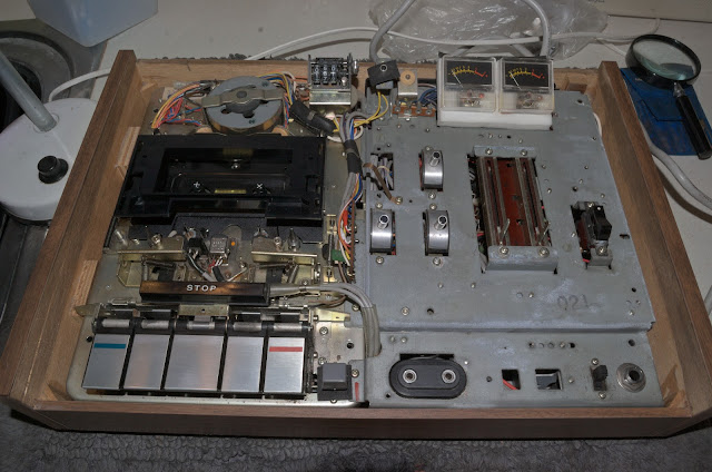
Here are some pictures after the deck had been cleaned. The blog pages will be modified as the weeks and months go by ...


No backlight for the VU meters - bulbs had failed.


Immediate Issues & Fixes:

Play turns off after about 1 second.

Reason: The capstan drive to take-up spool transmission and hence torque was lost due to the clutch rubber idler not engaging. Cause? - the mechanism's elbow/knee joint here has seized up!


Freeing the joint with isopropyl alcohol, later a light oil, then back and forth movement returned the mechanism to full operation - no more unwanted Stop!

Playback speed now was slow and inconsistent

Reason: The main square section belt drive had lost its ability to transmit energy efficiently - it was slack. Today I don't have the correct replacement, but I do have a smaller belt ~ 90mm diameter, 1.2mm x 1.2mm cross section. This works quite well, but a longer belt is on order!

Left & Right Pinch Roller Fixes

Both were cleaned - first with isolpropyl alcohol, then 'roughed up' with a fine grit paper, then cleaned again, finally Rubber Renue was applied.

Rolling the pinch roller back and forth along the 400 grit
sheet broke-up the surface of the rubber.

Hidden from view is a spring mechanism that applies a force
pushing the assembly up against the locating ring controlled
by the grub screw. The nut is gently tighten for a permanent fix.


Note: Since the height of the leftmost pinch roller and guide are adjustable, it was important to make sure the guide height was in the middle of the incoming tape.
 
The tape flow into, and out of the tape guide
should be as central as possible.
Test this by inserting the cassette for both sides A & B.
Also - the tape must not 'ride' against the sides of the guide.
 

The TC-161SD Play mode now stable. Fast forward and Rewind now functioning well.

Power Supply Servicing

Motor Run Capacitor: I will re-cap the whole power supply board, but for now I will want to replace the Motor Star/Run Capacitor. As can be seen, there are two settings - one for 50Hz, and a higher voltage for 60Hz mains frequency.

Switch Noise Suppressor: Also, I need to replace the ON/OFF switch 'back emf' or 'spark' suppressor. These can catch fire or smoke as I have experienced before.

General Electrolytic Capacitors: I have begun to replace the old electrolytic capacitors on the power supply circuit board. Checking them so far - the old caps seem fine, but I'll replace them anyway!

Remember, caution is everything, as this deck is possibly 48-50 years old!

New Motor Start/Run Capacitor:

Original Motor Run Circuit

The original Motor Run Capacitor,
which was measured at just over 1.2uF.
Note: an electrically isolating plastic cap has been removed here.


New Motor Run 1uF capacitor, with 450v rating in place.


A new CBB61 Motor Run Capacitor 1uF, with a 450v rating.
Note: 50Hz/60Hz switch removed, and the
higher voltage setting (cable) for 60Hz operation
has been isolated.


Warning: Replacing the Motor Run Capacitor can be a dangerous procedure to undertake if you are unfamiliar with electrical, or electronic work and diagrams. If you are uncertain, please do seek the advise and skills of a qualified technician or engineer. 

VU Meter Lighting
 
The old filament bulbs had failed, on inspection of the circuit diagram the voltage source was DC - which is easier to deal with. The DC supply is approximately 30v, and so adapting a DC circuit to suit should be relatively easy.   
 
First, the original circuit diagram -


Now, the updated circuit diagram -


Surface Mount LEDs used to illuminate the VU Meter display


Cassette Tape Backlight

The old filement lamps for 'tape progress' indication were replaced with LEDs working off a modified circuit.


Motor Speed

As suggested above, the speed was initially slow and very inconsistent. With new belts and a new 1uF motor run capacitor, the speed has stabilised, but is still incorrect. 

I have to date tried all three motor pulley diameters - much too slow, too slow, and too fast. The better of the two speeds from the three possible are still 'way off', perhaps as much as 5%, or even slightly more? I haven't measured, don't need to - it's obvious.

Solution: just realised what the problem was - I had put in a belt of approximately the correct diameter, but only 1.2mmx1.2mm cross section. This narrow belt had worked its way into the narrower area of the v-section of the pulley - effectively a narrower working diameter, thus providing a lower gearing ratio!, that meaning - a slower speed.

The middle pulley seems to be the engineered diameter for 50Hz mains frequency.
 

I need to find a 100mm ... 110mm diameter belt with at least 1.5mmx1.5mm cross section.

New Belts Arrived: So now I have a selection of square section belts - 1.2mmx1.2mm, 1.4mmx1.4mm, ~1.9mmx1.9mm, 2mmx2mm, and 2.5mmx2.5mm. Presently, I am unable to get hold of 1.5mm, 1.6mm, or 1.7mm belts.

Below is a set of results showing the playback of a 3150Hz tone, reference ABEX tape, and the various square belt cross sectional measurements -

1.4mmx1.4mmx102mm: 3050Hz (-3.17% error)

1.9mmx1.9mmx105mm: 3280Hz (+4.13% error)

2.0mmx2.0mmx110mm: 3275Hz* (+3.97% error)

2.0mmx2.0mmx110mm: 3295Hz * (+4.60% error)

The latter two belts were supposidely identical!?

The original square belt which is now slack, measures ~1.7mm x 1.7mm x 113mm and returned a test frequency of 3120 .. 3150Hz.

Since the belt had worked itself into a 'slack' state, steady playback was difficult to obtain, but we can see that speed accuarcy with this belt looked promising.

I still need to source a 1.6mm/1.7mm square section belt of around 100mm .. 110mm.

01/02/2022: New 1.6mm x 1.6mm, and 1.7mm x 1.7mm belts ordered - these should improve speed accuracy over the 1.4mm x 1.4mm belts? However, I'm not expecting a miracle, if I can get the TC-161SD to play within ±2% I'll be happy. Athough I would prefer the deck to run a little too fast, rather than too slow.

Blogger article is likely to be amended in the coming weeks and months. 02/02/2022

15/02/2022: New belts 1.7mm x 1.7mm x 101mm arrived.

The updated belt size vs capstan speed is now ...

1.4mm x 1.4mm x 102mm: 3050Hz (-3.17% error)

1.7mm x 1.7mm x 101mm: 3155Hz (~+0.16% error)

1.9mm x 1.9mm x 105mm: 3280Hz (+4.13% error)

2.0mm x 2.0mm x 110mm: 3275Hz* (+3.97% error)

2.0mm x 2.0mm x 110mm: 3295Hz * (+4.60% error)

Please note: a meter calibration resolution error of less than 10Hz (~0.3%) should to be taken into account for all measurements above. 

The new belt has given a surprising and very satisfying result!

Wow & Flutter?

Yes, there is audiable wow and flutter - higher than the quoted specifications.

So what are the potential sources of this unwanted wow and flutter?

Sources of Wow & Flutter

1) Belt too tight?

At 101mm, it may be a little too tight? Perhaps a diameter of 105mm-110mm would improve matters? At this moment, I cannot not source a 1.7mm x 1.7mm x 105mm..110mm (diameter) belt.

2) Traction between pinch roller and capstan? 

Now improved, both pinch roller mechanisms removed and cleaned, especially the bearings. Earlier I discovered some unwanted friction on the leftmost pinch roller.

Pinch rollers cleaned, and treated with Rubber Renue.

* Despite the work done, it is still possible that I need new pinch rollers?!

3) Slippy Capstans?

Thoroughly cleaned. Make certain no oil is creeping up the capstan shaft.

4) Motor and Flywheel Pulleys? 

Thoroughly cleaned.

5) Transmission line? 

The belt is 'in line' between motor pulley and flywheel. 

6) Vertical Flywheel 'Play' or Movement?

The flywheels are not experiencing any unwanted friction.

7) Excessive and/or constant friction in overall transmission chain?

8) Inconsistent elasticity along different parts of the belt?

{Hooke's Law: Deformation of a material is proportional to the force applied, within the elastic limits of the said material.  I sense that some belts offer inconsistent deformation along their lengths!? A source for additional wow and flutter???}

Take up Spool Tension & Pinch Roller/Capstan Contact
 
Later the idea came to me that the take up spool was possibly exerting too much tension on the tape? Specifically at the line where the pinch roller and capstan make contact, causing the tape to flutter intermittently?
 
The take-up spool tension can be adjusted on the TC-161SD (see a TC-161SD service manual), and reducing this has reduced flutter significantly! With a deck this old (c1972/1973) there is some mild pinch roller wear, often in the form of slight 'bowing' in the middle. Over all, grip is good.

17/02/2022: New belt 1.6mm x 1.6mm x 110mm fitted.

Just arrived today, this is the final belt I'll purchase for this machine. 

Big thanks to Donberg Electronics for selling so many belt variations.

Speed result: 3135Hz! and of course less overall belt tension, I'm very tempted to suggest that this is better than the 1.7mm x 1.7mm x 101mm I put on earlier!?

To recap -

1.4mmx1.4mmx102mm: 3050Hz (-3.17% error)

1.6mm x 1.6mm x 110mm: 3135Hz (-0.48% error)

1.7mmx1.7mmx101mm: 3155Hz (+0.16% error)

1.9mmx1.9mmx105mm: 3280Hz (+4.13% error)

2.0mmx2.0mmx110mm: 3275Hz* (+3.97% error)

2.0mmx2.0mmx110mm: 3295Hz * (+4.60% error)


Less than 10Hz (~0.33%) meter calibration error

has not been added/subtracted into the above figures.


Broken Grub Screw for Pinch Roller Assembly

Unfortunately the right sided pinch roller assembly's fixing screw ('grub screw') broke very easily. I had to drill the spacer/collar out and eventually replace (for now) with a series of nylon washers, with the 3mm (threaded) securing nut to set the height for the roller. I used clear nail varnish as a bonding agent so the nut will remain fixed in position.

Any unwanted movement will be detected when the two blue marks are out of line.


Wow & Flutter Issues Resolved? (13/02/2022)

Have I finally solved the problem of excessive W&F? Well, not quite - I initially thought so. 

The leading pinch roller seemed to be too high. Small but visible imperfections in the machining of the capstan's top end appeared to be transmitting some 'wobble' to the smooth running of the pinch roller>

However, I can still hear W&F, but more like a flutter especially in classical music, in particular pianos and slow moving strings etc.

Perhaps I ought to think about replacing the pinch roller?, I've done everything I can think of.


23/03/2022: New Pinch Rollers Fitted

The old pinch roller pins were 2mm in diameter but with a narrower section at one end. To remove them I had to partially, and carefully drill-out the 'rivetted' side of the pin. This also meant I had to later ream the existing hole to about 2mm in diameter - this was a delicate process.

The new 11mm x 8mm x 2mm-centred pinch rollers fitted perfectly, and are held in place using steel rivets with a 12mm length. Gravity and friction will hold the rivets in place.

With new pinch rollers fitted, the record head had to be physically re-calibrated for stroke, tilt, track height, and azimuth.

New pinch rollers, and steel rivets.

Removing the record head assembly proved difficult because of the 50 year old adhesive which had set quite hard. It was difficult to establish azimuth control which is why I removed as much of the old adhesive. I will later remove it all with pure acetone, but for now it works!

Capstan Re-Sanding (Do not do this!!!)

Some weeks ago I very foolishly applied 800 grit sanding paper for a handful of seconds to the capstans in a desperate attempt to kill the wow/flutter - big mistake!!! In doing so the capstan-to-tape slippage on the supply side became a little irratic - occasionally I would experience the tape lifting slightly up over the erase head. A another bigger problem soon became evident - the take up capstan and the pinch roller worked together in such a way that the tape began to ride up a little perhaps 1mm-1.5mm!

This completely upset the balance of the transport, the results were as follows - tape wouldn't erase properly in the right channel, head alignment had to be re-configured, and of course the tape ran above its normal line of travel. What a mess!

Solution? - carefully cut and shaped, then applied 3000 emery paper until I was happy with the 'finish' to both capstans. I did consider obtaining finer paper, but it wasn't required. 

(June 2022: Finer 5000 and 7000 grit paper was used to polish the capstans. All good now.)

After resetting the pinch rollers, erase head, and the record head - all was good again. Consistent high stability restored, even on C120 tapes!


Change in Tape Speed?

Back to this topic again! 

I suppose I can expect a small change in tape speed now that the capstans have been 'sanded' a little.

1.4mmx1.4mmx102mm: 3050Hz (-3.17% error)

1.6mm x 1.6mm x 110mm: 3135Hz (-0.48% error)

1.6mm x 1.6mm x110mm: 3125Hz ( -0.80% error)

1.7mmx1.7mmx101mm: 3155Hz (+0.16% error)

1.9mmx1.9mmx105mm: 3280Hz (+4.13% error)

2.0mmx2.0mmx110mm: 3275Hz* (+3.97% error)

2.0mmx2.0mmx110mm: 3295Hz * (+4.60% error)
 
Do allow some degree of error in measurements
and random speed variations which cannot be
accounted for, except perhaps a small change
in (UK) 50Hz mains frequency.

The WFGUI Program (Wow & Flutter Graphical User Interface)

For the first time I used the freeware application WFGUI.exe to measure speed and W&F. So perhaps this is more accurate than my meter?, even though it's calibrated to within ±10Hz.
 
Latest W&F: 0.14% - 0.20% (rms) poorish, W&F is audible on occasions. {Using: 1.6mm x 1.6mm x110mm belt}

Not sure why WFGUI varies on its W&F measurements? Although on examining 3000Hz sinewave playback traces on the oscilloscope, there appears to be transient breaks in the waves, and so may be misinterpreted by WFGUI?
 
Latest Speed Accuracy: ±10/3150 ~ ±0.3%, actually its within this figure, excellent!
 
The flutter is just noticeable when listening to slow solo piano music, typically as in J.S Bach's French Suites.

Record/Replay Head Azimuth Quirk

Setting the head azimuth on all my machines (including this TC-161SD) to my ABEX 10Khz full track reference tape - all machines record to, and playback from each other with correct azimuth. Allowing of course,  for very minor drifts in phase between left and right channels at 10Khz.

However, this TC-161SD needs its azimuth screw turning clockwise for about 1/8 of a turn when recording to, and playing back from other decks! Why? - I cannot answer this definitively, but I suspect head wear on this TC-161SD may be responsible for this abberration. This is not the situation now. Azimuth stability and compatibility with other machines is very good! I did some extra 'polishing work' on the trailing capstan. (04/10/2022)

(11/04/2022)

Drive Belt Dilemma

I suspect that in the 1970s square section belts were eventually abandoned in favour of flat belts? And for good reasons too - 
  • Flat belts probably yield lower wow & flutter figures?
  • Flat belt thicknesses are often much less than a square section  thickness - allowing us to predict tape speed? Observe above variabilities in tape speed with square section thicknesses, and ±5% excessive speed errors are easily obtained.
However, since this is an early TC-161SD model it is fitted with a square section belt system, so I'm stuck with it! Ultimately, square section belt thickness is going to determine how close this deck will play to the ideal of 4.75cm/s.

Finding a suitable belt has been difficult - the optimum belt square section here being about 1.6mmx1.6mm. If I had the choice, I would like to fit a slightly larger diameter belt of between 112mm and 116mm. This would also lower wow & flutter figures, as tests have revealed.

Currently I am searching for belts in the range of 1.6mmx1.6mm (or 1.7mmx1.7mm) x 112mm to 116mm in diameter.

I have one such belt on order - a 1.7mm x 1.7mm x 116mm. Let's see if this works any better!? I don't mind a cassette deck running a little fast, if this meant that wow and flutter figures are lower than 0.2% wrms, I'll be satisfied.

(4th June 2022)

Motor Inspection and Lubrication

While waiting for a 116mm diameter square belt, here is a photo of the induction motor. Stator and field windings, rotor, spacers, bearings, and cap. Note - the cap has an additional plastic adjustable threaded cap.

A new '4mm x 12mm x 4mm' sealed bearing has been fitted. On the motor shaft there are brass/carbon spacers. Surprisingly, replacing the brass-carbon-brass shim washers the other way around on the rotor shaft resulted in 'noisey' motor action, not sure why!? Sounded similar to two sheets of paper rubbing gently together. All is fine now, except for wow and flutter figures still appear to be too high; 0.12% .. 0.18% DIN? according to WFGUI.EXE. It seems that the belt's W/F figures do improve with use, but this 161SD is quoted to have a W/F of about 0.1% DIN?
 
Still awaiting the arrival of slacker 1.7mm x 1.7mm x 116mm belts from Portugal. They have arrived here in the UK, but I fear may have been lost???

Lower: Four pole-pair field windings in the Stator.
Top: Rotor with brass/carbon spacers
Right: New sealed bearings.
Right: Motor End-cap and adjustable nylon(?) cap.


14th June 2022

New Belts Arrived: (08/07/2022)

About 2 weeks ago the new belts arrived - many thanks to Web Spare Parts!


Received: two 1.7mm x 1.7mm x 116mm and two 1.6mm x 1.6mm x 110mm flat belts.

Unfortunately the 116mm was too long, although the belt did run the deck okay, and wow and flutter was indeed lower. However, a 116mm diameter belt is too big for this early model of the TC-161SD - I would not recommend purchasing one.

The optimum square belt diameter for an early production run of the Sony TC-161SD would be between 110mm to 114mm x 1.6 mm x 1.6mm.

*********************

27th Sept 2022

Pre-Emphasis Modification

A small but significant modification was made to the 'record EQ' circuit, otherwise known as pre-emphasis.

There was a minor problem with sibilance distortion (seemingly common with some old Sony tape decks?), which was rectified by cutting the amount of pre-emphasis on record.

There is a small, and simple LCR series circuit in the emitter leg of Q108/Q208 which forms part of the feedback loop which shapes the effective gain with frequency. The voltage gain of this circuit can be expressed mathematically in the form of a transfer function. However, without going into the details, pre-emphasis can be cut by lowering the value of capacitor C135/C235 in the LCR leg, and this is what I did. The original service manual circuit diagram states that C135/C235=47nF, but in circuit was a 39nF capacitor! Did Sony later realise there was too much high frequency pre-emphasis!?

My solution was to lower this again to 33nF.


Sibilances and general high frequency audio content is now clean - very pleasing on the ear. Even 'aggressive' CD high frequency content is controlled when normal recording levels are employed.

Later a small amount of bias 'tweaking' was done, and now this 1972/1973 Sony TC-161SD is capable of delivering slightly better than 40Hz to 15,500Hz ±3dB at recording level of around -20dB or a little higher.

'Timing' Switch Problems (18/12/2022)

There is a multi-switch that activates when Play/Play+Record is pressed.

Without going into the details too much, an auto-stop failure began to emerge during the end-of-tape state during Play. After analysing the System Control Circuit, I took the precaution of replacing all the remaining electrolytic capacitors that I hadn't replaced, and the C945 (2SC633A according to the SM) transistors that were already in circuit. The signal diodes were also replaced with 1N4148 types. 

Result: no change, the system would not auto-stop at the end of the tape.

I then traced one of the 'timing' switches (S3-4) which was intended to 'earth' one side of R415. I carefully and deliberately 'shorted' this on the system control side and saw that the auto-stop function (during Play) worked! I concluded that the 'timing' slide switch was not functioning correctly. Now was the time to open up that switch and perhaps re-work it so that contact would be made.


This slide switch is a 4-pole, double throw mechanism, commonly termed '4PDT'.

The slide switch was removed and desoldered from the small PCB. I then opened it up carefully; it's quite an easy task.

This 4PDT slide switch is a 'make before break' switch.

The internal contacts and the spring contacts were 'cleaned' with fine emery paper and later switch cleaner. The switch was then re-positioned into this PCB and re-soldered.


The dark patch is a coating of clear nail varnish.


Well, was it successful? Initially yes, but later the auto-stop in Play mode became a little unpredictable. I cannot be certain it will work consistently; it tends to work if I 'nudge' the switch.  All other 'timing' contacts seem good; another two are for audio muting as highlighted in the circuit diagram below.
 

I've decided to order some
TE Connectivity PCB Slide Switches: Four Pole Double Throw (4PDT). We shall see if they prove to be a success!?
If not, I need to look further!
 
20/12/2022: A new TE Connectivity 4PDT slide switch was installed, but first I had to remove the 'latching' mechanism from the slide switch.


The auto-stop function for Play action now works well. Although, I'm still not 100% certain that the problem was solely due to the old switch.
 
Speed and Wow & Flutter Update (27/12/2022)

After resetting the alignment of the 1.6mm square section belt so that the motor pulley, belt, and flywheel were in line with no perceptible deviation, I finally obtained the following figures. Also note: the belt and pulley was cleaned again with denatured alcohol. 
 
(Figures below are based on an ABEX 3150Hz Test Tape, and 100 data samples from WFGUI.EXE's 'LOG' file):
  
Mean Speed: 3147.54Hz
Mean Error: 0.08%
Standard Deviation: 1.25Hz
       
Mean Wow/Flutter: 0.15% DIN
Standard Deviation: 0.0183%

I'm certain that if the motor pulley 'contact area' was higher, better wow/flutter figures could be obtained. Re-cleaning the pulley, and the belt especially brought wow/flutter figures down a little more from around 0.18% DIN.

I'm tempted to experiment and put in a larger cross-sectional belt, just to see how this affects wow and flutter figures.


21/01/2022 Wow and Flutter Update:

This can be reduced further if I allow the Sony TC-161SD to be running for 15 minutes or more. A figure of 0.134% DIN was recorded from a sample of 200 readings from WFGUI.EXE. Draw your own conclusions why this is; my immediate thoughts were temperature rise, humidity variations, which all affect uniformity in belt elasticity?  

Update: 06/04/2024

Firstly, apologies to readers of this article. I have deleted most of what originally followed after this sentence. The reason was simple - I'm still casually working on this TC-161SD deck, and finding various factors that lead to changes in wow and flutter. One such factor which was not immediately obvious is now partially explained.

One Definite Source of Wow & Flutter: (06/04/2024)

On inspection of the FF/RW idler and associated mechanisms, I did notice that spinning (by hand) the axis of the idler gear was easy when in an 'upside down' position (as shown below), but then it gained friction when inverted!? And of course when the 161SD is playing normally, this friction is going to become potentially troublesome for the motor - effectively adding an additional and intermittent load?


The whole FF/RW mechanism was disassembled, thoroughly cleaned, and lubricated, and what followed was a distinct improvement in the consistency of wow and flutter. Rather than being highly variable between tests.

Until I have narrowed down all the factors that lead to excessive wow and flutter, I shall not be making any more contributions to this article.


06/04/2024.


Saturday, 27 November 2021

NEAL 102 & 103

 NEAL 102 & 103 Transcription Cassette Decks


Taken from the 1976 HiFi Year Book.


Saturday, 2 October 2021

AKAI CS-705D

The AKAI CS-705D

Original ebay Advert Images of the CS-705D.
 

Advertised for 'parts or not working", I got this little attractive looking deck up and running in less than 30mins.

However, there's much work to do on it - the record head was quite thick with dirt and oxide, and the pinch roller looked as if it hadn't been cleaned for decades. The CS-705D was a little corroded internally in places, but in fair condition. The VU meters were misbehaving on Play.

So far ...

  • Removed internal debris
  • All contacts and switches cleaned with Servisol Super 10
  • Capstan shaft lubricated with Revox recommended capstan oil. 
  • Pinch roller - removed all tape oxide with diluted acetone, later isopropyl alcohol, and finally water. Roughed-up surface by rolling pinch roller on fine grit paper, removed excess rubber (vacuumed), then applied some Rubber Renue.
  • DC Motor (dated Nov 1976!) removed, applied Servisol Super 10 down the shaft. The fitting appeares to be standard, and so a replacement may not be difficult - looks like a 2mm spindle? 
  • Cleaned associated motor pulley.
  • All muting and similar switches cleaned.
Measurements -
  • Erase head bias frequency/voltage: ~85Khz/~35v peak.
  • Record Head bias frequency/volatge: ~85Khz~9v peak.
 Observation -
  • Electrolytic capacitors seem good, may replace later?

The deck is now functioning, recording, and playing back almost as new.

Issues to be Addressed

  1. Record/Replay Head replacement or lapped? So far - recording and playtback are fine, much better than expected, but the head wear is obvious. 
  2. Motor speed seems to drift over time?

11/10/2021

A New Record/Playback Head Installed

Original Record/Playback head -

This doesn't appear to be the original P4-303 or
HN-424822 record/replay head?
Head wear is actually deeper than it looks in this photograph.


Although the old head worked well it had obviously done some miles, so I chanced a few potential replacements. Looking at the two 'new' heads I bought, and the original head fitted in the CS-705D, I decided to perform some measurements.

The results are listed here ...

(a) Original: '512 K6AB', R ~ 192Ω, L ~ 110mH (at 10Khz)

(b) New: 180-T1905, R~250Ω,  L~ 78mH (at 10Khz)

(c) NOS: 445-20 E S1X10, R~ 350Ω, L ~ 127mH (at 10Khz).

Again, I suspect the 'original head' was not the exact one that came with this machine back in 1976? (Edit: It may indeed be the original, as other images of the CS-705D on the internet show the same record head identity number.)

Head Capacitances: While it is true that the inductance value L should be independent of excitation frequency, we have to appreciate that a record head also has parasitic capacitances, which is why (I suspect) that the apparent measured inductance varies a with test frequency?

Before I decided to replace the head, I measured (under load) the peak head bias frequency voltages in record mode on the CS-705D. They were ...

Type I (Normal Tape): default 9v, (can be varied from 5v to 18v)

Type II (CrO2): 14v, (can be varied from 7.5v to 26v)

Type III: Fe-CrO2: 12v, (can be varied from 7v to 24v)


Calculating 'Normal' Bias Record Head Current

From Ohm's Law, we have I = V/Z, and for our existing record head the impedance at approximately 85Khz is going to be -

where Z = {R²+(2πfL)²} ~ 59,000

It should be noted that the impedance from the inductor L is frequency dependent and dominates the overall impedance Z.

From this 59KΩ impedance, both peak and RMS bias current can be estimated -

Original '512 K6AB' Ibias ~ 0.15mA peak, or 0.108mA RMS.

Ibias is the high frequency bias current that will flow through the head, even when there is no signal applied during recording. Any additional audio signal added to the bias is very small in comparison.

Which 'new' Head to Choose?

Good question - I don't have the defintive answer, but I decided to try the 180-T1905 first. At 85Khz, its impedance was going to be lower since its inductance was less.

Ignoring the internal DC resistance for this calculation, Z ~ (2πfL) ~ 41600Ω, and so the bias current from the 'new' 180-T1905 head can be calculated, and found to be 0.15mA - almost identical!

After fitting the 180-T1905 head, all that was left to do was to - demagnetise the head, re-set the azimuth, re-calibrate PB levels (from a Dolby Level reference tape), adjust the internal record levels so that 0VU on record, gave back 0 VU on playback. And then finally alter the bias (actually bias amplitude!) from the potentiometers on the circuit board.

Success? ....  yes, excellent!

The AKAI CS-705D records and plays back very well indeed. It's 333Hz and above frequency response is almost flat to 13,000Hz, and about -3dB down at 15,000Hz. This is better than the original specification.

I haven't yet arrived at the point where I will undertake a full frequency response test, and weighted signal to noise ratio assessment.

Track Height Adjustment?

Possibly later I will add a fine shim and test for true track height alignment using one of my Nakamichi 3Khz track height test tapes.

 
14/10/2021: Both with, and without a shim added, I measured the output peak-to-peak from a 3Khz Nakamichi-DR10-made track height test tape. The difference was small, but with the added shim the playback amplitude was slightly greater. The head tape guides are now truly equidistant from the tape. So the shim stays in!

Motor Speed Variatons.

As mentioned above, the motor speed controller appears to let the motor drift off speed. It's not serious, so I will look into subject at another time. 11/10/2021.

14/10/2021: Old Motor Refurbish Attempt

I took the old motor out, and stripped it down to the bare motor assembly, then fired some more Servisol Super 10 down into the armature/stator chamber, just to be sure its truly contact cleaned! 

Also, as a precaution I desoldered two electrolytic capacitors on the motor speed conroller board, then replaced them with new 3.3uF and 4.7uF capacitors.

All re-assembled, and (so far) working well. Again, I speed-calibrated the motor, so only time will tell if I have found the source of the problem?


Motor Casing.

Note: There is a removed sheath that electrically
isolates the casing - not shown.


DC Motor Controller Board - can be removed by desoldering at X-points.
Note: Polarity is important, otherwise the motor will run clockwise
- currently, it runs CCW (counter clockwise).

The best way to de-solder is to use a copper braid which 'soaks up' the molden solder during de-soldering.

14/10/2021: The motor was again starting to drift in speed, in a similar manner to the motor that was originally in the AIWA AD-F770 - the change was slow but noticeable.

15/10/2021: New Motor Fitted
 
Mabuchi (a copy?) CCW 2400rpm motor now fitted.
Runs off 12.6v DC supply, 12.6v under load conditions.
 
Played the CS-705D for more than an hour - all working well, stable sound. 
 
Motor Speed Drift 17/10/2021: The speed seems to drift again - it's very subtle, but noticeable. Confirmed this when I had to recalibrate the speed using a 3Khz calibration tape - twice. So I am not imaging it! 
 
Power supply is stable, so my attention is on (a) the new motor, (b) pinch roller and possible slow motion slippage? (c) Excessive belt tension? - motor load current is higher than expected Play=ON ~150mA, FF=ON ~260mA, RW=ON ~250mA! 

Comparing DC Motor Load Currents
 
Here I've compiled a small table of results comparing DC motor load currents with a TDK D46 tape inserted. 
 
Bare in mind, the torque (Torque = tangental force x radius) developed by a motor is proportional to current, ie T ∝ I. Example: A doubling of armature current is required to drive a doubling of load torque.

Cassette Deck Model

Play Current

FF Current

RW Current

AKAI GX-M10

~ 57mA

65mA … 74mA

59mA … 106mA

NAD 6050C

~ 68mA

72mA … 90mA

71mA … 120mA

AIWA AD-F770

69mA ... 75mA

NA

NA

SANSUI SC 1330

~ 54mA

98mA …135mA

103mA … 170mA


AKAI CS-705D

(before belt stretch)


~ 150mA


200mA

± 50mA


250mA

± 50mA


AKAI CS-705D

(after belt stretch)


120mA ... 125mA


200mA

± 50mA


250mA

± 50mA


We can immediately see that the current required for the CS-705D is more then twice that for other machines. Indeed, after deliberately and uniformly stretching the flat drive belt in the CS-705D, I was able to bring down the average Play current - but this is still too high.

I can only conclude for now, that the loading on the small DC (internally speed regulated) motor is beyond the specification of the motor!? Hence the reason why its speed 'wobbles' or drifts as it gets warm. Or is it more likely that the motor and internal speed regulator circuits are failing?

New Old Stock (NOS) Motor: Matsushita MMI-6S2LS

29/10/2021 

After trying several NOS (New Old Stock) 12V DC motors (a genuine Mabuchi, and a 'Mabuchi' Chinese copy), I finally installed a 1994 unused Matsushita MMI-6S2LS. All motors of course include their respective motor speed controller circuits. 

After 2 hours play, no problems to report, and no large current drainage!


The torque now demands currents of -

Play: 76mA ... 83mA, FF: 150mA ... 180mA , RW: 150mA ... 200mA

The above figures are dependent on which spools have the most tape on them. Any excessive tension applied by the belts will also increase Play, FF, and RW torque currents. 

One fact that struct my attention, was the internal 'slip' friction (and additional torque load) demanded by the take-up spool. The CS-705D has a strong take-up spool force, which when in Play mode, adds about 20mA. This means that when in Play + Pause mode, the dc current is only about 57mA/58mA.

Speed Calibration

Using an ABEX 3150Hz reference tape and frequency counter, I have the deck set up to playback somewhere between 3150Hz and 3160Hz - which is slightly fast.

Hopefully, this time the motor speed won't start to drift!


********************


Note: Long exposure photograph.

31/10/2021

LED Illuminated VU Meters

I decided to change the old filament lamps for white LEDs. However, the original lamps worked off a transformer ac tapping, whereas any new LEDs in circuit will need DC to get them working without flickering.
 
The proposed modifications and circuit is - 


VU Meter LEDs ready to be used.
Note: all exposed wires were electrically isolated
after this photograph was taken.

The LEDs now in circuit are not working to their full brightness, they don't need to. Two LEDs in series for each VU Meter is sufficient, where each LED is only consuming between 6.0mA and 6.3mA. Some 12.4mA of dc current was observed which will split into approximately 6.2mA x 2, since this is a parallel circuit. 

The two original 1000uF (25v rated) electrolytic capacitors were replaced by larger 3300uF (actually ~2900uF) capacitors. The idea behind this was to increase the available charge for both the 'new' DC motor, and Q1 voltage regulator circuits.

As a matter of interest the AC fuse currents were measured at F2 and F3 - they were approximately 188mA (before the LED circuit was introduced), and about 107mA for the DC motor circuit in Play mode.
 
All working well - very nice bright and clear VU Meters!


Cassette transport speed is still very stable!

Other Images


Playback EQ (De-emphasis) Modification (12/11/2021)

A small change to the playback (PB) equalisation circuit and curve was made to help compensate for any new record/playback head that I fit.
 
All electrolytic capacitors in the area were also replaced.

The resistor R12 is now a 20kΩ variable trimmer
potentiometer set to about 10kΩ by default.


AKAI Record/Playback EQ
 
I do not have any Akai alignment tapes, so the earlier record and playback EQ specification adopted by Akai is unknown, but I can assume it probably approximates closely to a 1970s IEC standard, but with slight modifications to suit their designs and record head constraints? The same probably applies to Sony, Pioneer etc?
 
Using a Home Made IEC 1981 Reference Tape
 
Using a home-made (approximate) IEC 1981 specification alignment tape using the Nakamichi DR10, I set the playback response of the AKAI CS-705D to approximately -6dB at 10Khz in comparison to the output at 333Hz/400Hz.
 
Why -6dB at 10Khz?
 
Nearly all the (pre-Prague 1981 IEC standard) second hand decks that I've bought exhibit a -6dB (±2.0dB) output drop at 10Khz (reference to 315Hz/333Hz/400Hz levels) when playing back the home-made IEC 1981 reference tape, created with the Nakamichi DR10. 
 
Since my Nakamichi DR10 has not been used extensively, I feel reasonably confident with the general accuracy of this setup. To support this proposition, my (post 1981) Revox B215 and even a humble Marantz SD-35 follow the Nak DR10 playback curves reasonably accurately, to within ±1.5dB at 10Khz.

Just to reiterate, I simply use the Nakamichi-made 'IEC 1981' tape as a general playback guide at 333Hz and at 10Khz only, it is not a reference tape for older pre-1981 machines.


Article is subject to small changes, additions, and corrections without notice. 14/11/2021.


cassettedeckman@gmail.com