Sony TC-134SD
About 3 weeks ago, I purchased this from a charity shop for £8.50 + £5.50 postage, but I donated an additional £15 as it was for a children's hospice.
After many hours of restoration work, the unit is now working well.
However, there seems to be no internal circuitry dedicated for chromium dioxide tape record bias (bias frequency amplitude) or playback equalisation, despite the 'Cro2' setting? There are however, recording pre-emphasis circuits for both 'Normal' and 'Cro2' chromium dioxide tapes.
Quick Summary
Well, I've restored the machine to good working level - but not totally satisfactory.
A complete clean of all switches, a complete recapping of all electrolytic capacitors, some mylar capacitors, and full transistor replacement has been undertaken, including the dolby circuit. Even the bias oscillator transistor, resistor, and capacitors were replaced.
However, four issues still remain.
(1) Cro2: No apparent circuitry for satisfactory use of Cro2 tapes? While the Cro2 switch activates to shape the pre-emphasis for Cro2 use, there are no changes in the amplitude of the Cro2 bias frequency 'carrier'!? The bias frequency carrier for Cro2 tapes is usually higher, or was this standard practice back in 1972? Nor does the Cro2 switch activate an alternative playback EQ, ie Cro2 de-emphasis.
(2) Frequency Response: Poor playback, and record frequency response - less than quoted in the specification. After some considerable investigation I strongly suspect the Rec/Replay head is the problem?
(3) Low-level Record Noise in Left Channel: Very low-level, but intermittent additional white noise ('hiss') in the left channel after recording. It almost sounds like 'drop out' white noise. The source of this is still a mystery, but the recording audio stages are not to blame. Some tapes record a louder 'noise' than others. This noise is not present when recording with Cro2 or Type II tapes? This has raised general Normal/Cro2 questions - I have not yet studied the machine for general Cro2/Type II tape useage. So perhaps the answer is somewhere there?
Incidentally, this noise that I refer to is an additional, audible noise much like broken 'hiss' when Dolby is set to OFF. It could also be described as slightly quirky - almost as if it was radio frequency interference.
(4) Tape Transport Speed: A speed check revealed that the induction motor is running 5% too fast. Alternative motor pulleys with a shorter radius may not be available?
This is the current state of the TC-134SD.
27/04/2021. (See later 03/07/2021)
Higher than Expected Recording Bias Noise (08/05/2021)
After much investigation, but by all means not fully conclusive, the excessive intermittent bias noise as described above may be solely the result of this deck's record head being heavily under-biased!? Although, I'm not sure why?
As part of my investigation, I de-soldered the original bank of bias capacitors and replaced the circuit with two (high voltage) variable (10pF .. 60pF) trimmers. I am now able to vary the 83Khz bias frequency peak voltage between about 5v and 40v on entry to the record head.
 |
Original Circuit.
|
 |
Modified Bias Circuit (subject to revisions).
|
 |
The old capacitor bank was de-soldered and removed.
Two high-voltage rated variable trimmers were soldered
in parallel so that their effect is to add,
ie, (10pF .. 60pF) + (10pF .. 60pF).
|
 |
Bias Frequency Carrier at approximately 18v peak.
|
The Sony PF145-3602A head employed in this machine is also used in other Sony machines. Of note - their bias voltages are approximately 40v (rms?) - which suggests that the TC-134SD I have here is under-biasing on recording?
Theory Reminder
A typical tape head magnetisation curve is show below. The graphs show B vs H, where B is the magnetic field (flux) density, and H is the 'magnetising force'. H is a function of I, where I is the current.
 |
Note: The non-linearity of the B vs I
|
 |
Simplified Record Head Diagram.
B field (Webers/m^2)
H (Ampere Turns)
|
The record signal 'sits' on the Bias Frequency Carrier.
Is this low bias deliberate?
Well, I'm not sure, but it appears to be so, as the pre-emphasis circuit components are all correct as indicated in the service manual. Also, the bank of bias capacitors found in circuit are also as stated in the service manual.
Playback Flatness: An internal playback EQ potentiometer can be adjusted to obtain a reasonably flat playback response to about 8KHz/10KHz. Playback frequency flatness was checked using both a Nakamichi DR10-made, and a Revox B215-made frequency sweep tape, from 333Hz .. 10Khz.
The Probable Source of Additional Intermittent Bias Noise?
Before I explain my theory as to why the deck experiences this added low-level interference here are some observations I made -
Decreasing Bias Amplitude: If I decrease the bias frequency amplitude down to 10v or lower - the excessive bias noise disappears, which I expected as only the erase head 83Khz high frequency erase signal is now responsible for tape hiss.
Increasing Bias Amplitude: If I increase the bias frequency amplitude to over 30v (peak), again the distracting additional bias noise also begins to fade away - leaving only erase noise and an expected 'clean' bias noise from the record head to be present. However, there is a cost to raising the bias higher - the recorded treble 8Khz/10Khz levels diminish.
The intermittent excessive bias noise issue only persists for bias amplitudes of around 15v ... 36v, peak. However, not all Type I ('Normal') tapes exhibit the same excessive bias noise - but there a general problem here nonetheless.
The thought then crossed my mind that older 'Normal' cassette tapes generally require lower bias to work optimally - so perhaps the TC-134SD was set up this way?
Compromises
In the service manual '7.5Khz' (not 10Khz, or higher) is mentioned as a reference point in achieving correct bias calibration, that is - a flat response to 7.5Khz. Most 'newer' Sony decks make reference to the amplitudes of a test signal at 1Khz and 10Khz as a guide to correct bias calibration.
So I decided set the bias to mirror the frequency response expectations of this deck. I have now set the recording bias so that I can acheive 100Hz .. 8Khz to within -3dB. This increasing of bias (but lowering of recording frequency response) has substantially lessened the distracting added recording bias noise.
Head Wear Consequences
Now, here's my theory - although the record head on this deck shows almost no visible wear, there is wear - it is extremely small, only under a x8 loupe can it be seen.
Tape head wear impacts on the head's ability to record to the tape, and I am beginning to suspect that random microscopic air-gap regions between the head and tape now exist for his machine. This implies that even recording bias noise (not to be confused with erase head erasure white noise) is going to be affected - and why not? If a tiny air-gap is introduced into the magnetic circuit, then permeability will suffer, hence the strength of B field will suffer too.
Currently, I have set both left and right channels at the head to receive 40v peak bias at 83.3Khz. I was tempted to increase bias to a higher level, but the TC-134SD's treble response would have been unbearable.
The revised bias and oscillator board is shown -
Circuit Board Components and Small Revisions
Below shows a copy of the main circuit diagram with some alterations, including comments/references I made at the time.
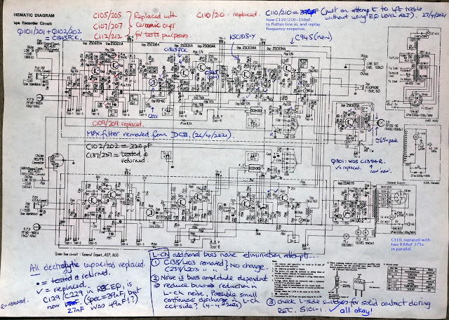 |
A mixture of C1845, C1815, and C945 NPN transistors -
I didn't have sufficient amount of C1815s at the time, so C945s were used.
All replacements were made in pairs.
|
Line In Response at 10Khz
I noticed quite early on that the 134SD exibited high frequency drop of around 2dB/3dB at just 10Khz!? This was tracked down and found to occur before the signal entered the dolby circuit and indeed before the MPX filter. Intuition suggested that I should lower C110/C210 below the rated 220pF, and so I replaced this for 150pF. Now the dip in response is around 1dB.

Increasing Transistor Bias at Pre-emphasis Stage
Within the recording pre-emphasis circuit, I increased R137/R237 from 330KΩ to 300KΩ. Reason? - to forward bias the transistor a little more, there was an issue with the cleanness of the treble. This action resolved it.
14/05/2021
Additional Images
Sony PF145-3602A Head
I hope one day to be able to replace this head for another similar, or failing that - take a chance and get this head re-lapped? I am intrigued by this additional and distracting bias noise.
One other matter to resolve too, is to replace the pinch roller. I also suspect the pinch roller is not applying the same amount of tension at the edge of the tape, as left-channel oscilloscope traces seem to suggest?
Final Bias Circuit (17/05/2021)
After much experimentation, I've decided to re-do the bias circuit and accept that this deck has limitations, and a probable minor problem with head wear, particularly in the left channel?
I've finally settled for a record/playback frequency response to 8khz at approximately -1dB, where at 10Khz the record/playback response can dip to about -4dB! Lowering bias achives slightly better results to about -2.5dB at 10Khz, although at the expense of the excessive bias noise as indicated above.
The excessive intermittent bias noise varies from tape to tape, while TDK D (1990s versions) are very low and acceptable, earlier TDK D (1980s) present listening problems.
The revised bias circuit now allows me to alter bias frequency from about 15v to just over 40v, peak.
Tape SpeedOne remaining issue which has not been resolved is the high tape speed on this TC-134SD machine. It is somewhere between 4% .. 5% too fast.
===================
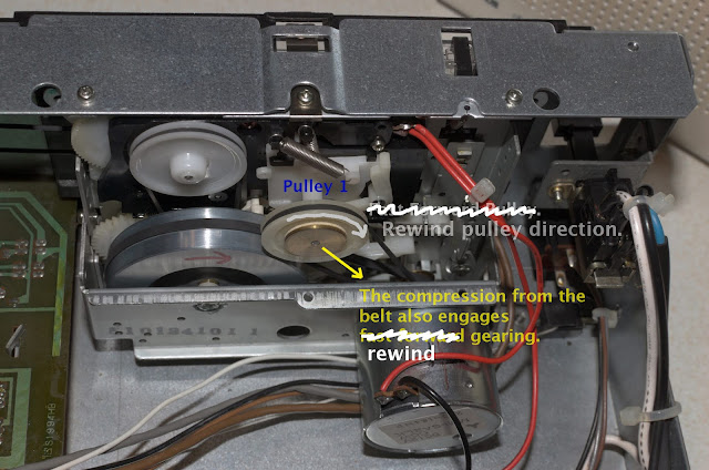
Pinch Roller to Capstan Issues (22/05/2021)
Ever had problems such as chewed up tape? Well, you're not alone!
Changing my old pinch roller for a new one presented problems - more than I will write about here. However, it is worth observing one of the main causes of crimpled tape is down to a poor, or worn pinch roller, misalignment, or excessive tape tension cause by the take-up spool.
 |
The ultimate test for uniform traction?
Observe tape flow stability before capstan-tape-pinch contact!
The most stable system can be observed when there
is no tape pad. Tape pad can and does increase stability.
|
The old pinch roller had to be replaced - it was uneven, although wasn't creating too many problems.
After extracting the old 2mm steel pin (had to drill it out!), I initially settle for this solution -
It worked well, but using a steel bolt with a thread acting as both support and guide for the pinch roller troubled me, so I decided to use a NOS (New Old Stock) 2mm steel pin in the existing assembly -
Sufficient Pinch Roller Force?
As a matter of interest to me, I compared the pinch roller forces on the capstans of several other cassette decks, and found many of them to be high - higher than I initially assumed!
Currently, this latest solution for my TC-134SD exerts plenty of pressure, tape flow into the capstan is very stable with a tape pad.
Stability with No Tape Pad
However, as a real test for stability, and without a tape pad - tape flow stability is lessened, and if I allow Play to continue beween 5 and 30 seconds (sometimes minutes), the tape may 'ride up' the capstan and crimple the tape. This is resolved by adding more force to the pinch roller - the tape then 'rides down' the capstan and tape flow is stable once again. The reason this happens in this example is simple - excessive tape tension! Any engineered reduction in tape tension will return the non-tape pad cassette transport to stability.
Pinch Roller & Tape Summary
If you have transport stability problems, check ...
(a) pinch roller/capstan general parallel alignment (usually okay)
(b) pinch roller wear - the roller has to be 'grippy', its cross section must be unchanging.
(c) Tape-up spool tension - is this excessive?
(d) Too much 'play' in the pinch roller's axis?
***********************
Subject to the correction of mistakes, and additions.
22/05/2021.
*********************
New Motor Run Capacitor Installed (06/07/2021)
The previous 1uF 250V motor run capacitor seemed to be fine, nevertheless I chanced a replacement rated at 1uF 450V ±5%, and the deck now runs about 2% fast, messured via an ABEX 3.15Khz test tape and frequency counter. Compared to previous measurements of 5% too fast - a much better result!
 |
The Original Metalised Paper 1uF 250v ac rated Capacitor.
|
 |
New Motor Run Capacitor
|
I can only assume the phases of the rotating magnetic fields for this induction motor were not complimenting each other, forcing the motor to rotate at about 5% too fast? Even at a 5% increase in speed, music and speech recorded on other machines sounded almost a semitone higher in pitch and at a correspondingly higher tempo.
06/07/2021: New Rewind counter belt fitted, very fiddly job!
Approx 15/07/2021: Chinese brass-centred pinch rollers now replaced by an original Sony pinch roller. No observable 'wow' on recordings. The Chinese roller (for some reason) would frictionalise, causing excessive 'wow' - not sure why?
Bias Traps (19/07/2021)
It is very difficult to completely eliminate the high frequency bias carrier leaking into the final stages of the record section. My attempt to minimise leakage completely was to replace the bandstop filter (C138/C238 100pF in parallel with L103/L203 33mH), with an effective variable capacitance. I chose a 75pF (250v/500v rated?) capacitor in parallel with a 10pF-60pF trimmer and was able to minimise leakage to about 145mV in one channel, and about 125mV rms in the other.
I cannot remember exactly what the previous leakage voltage was, but I think it was rather high at ~ 400mV rms? Also, as the inductors L103/L203 were not air-core types, crossover distortion was observed - very similar to that seen on the bias traps for the Revox A77.
The 'new' Bias Trap is shown.
Note: The new revised circuit for general bias is not shown here, see Modified Bias Circuit diagram above.
So far, so good!
29/11/2021: Since the above bias modification was done, the bias adjust has been re-wired with two capacitors in series. This has lessened the threat of potential voltage breakdown across the 10pF/60pF trimmer.
Current 'To Do' List
- New 25mm diameter x 1mm/1.2mm square section belt for the auto-stop feature. Done Sept/October 2021!
- New narrower flat section capstan-flywheel drive belt needed. The current belt is too wide - this excessively wide belt tends to shift to one side of the capstan flywheel, and as a result may effectively be driving the capstan above its designed revs/second? I think differently now. It's fine!
15/11/2021: Since the above was written on bias circuit modification, I have partially changed the set up. More to follow at a later date.
15/11/2021: New Pinch Roller Assembly
The deck was beginning to suffer from serious wow and flutter issues, and although I replaced the old assembly with various chinese pinch rollers combined with other modifications, I also decided to purchase a new-old-stock pinch roller assembly for the TC-134SD. I bought this from the US.
As can be seen the head assembly plate rides on three bearings, but the strange thing is - the centre collars appear to dictate the head assembly plate height!?
I later experimented by replacing the default 2mm bearings with 2.5mm versions. All appeared to work well - very stable, but I was not confident that the larger bearings were not effectively raising the overall head height? - which I didn't want!So at this moment, the plate bearings are 2mm, the default diameter according to the service manual.
 |
Observant viewers will see that an e-clip
was not securely pushed on -
it is now since this images was taken. ;o)
|
 |
Since this photograph was taken, an extra shim
has been placed under the record/playback head.
Head height was determined using a Nakamichi made
3Khz test tone tape.
The erase head has been 'relapped' 800 grit paper -
I have no finer grade paper,
but it didn't matter, it's working very well.
|
The assembly is very stable, wow and flutter is not an audible issue.
Blog/article is subject to the correction of mistakes, and additions.
15/11/2021.29/11/2021


