The Sony TC-K45
An Attempt at Restoration
- 17th November 2020: An on-going progress report.
- 2nd January 2021: Closure.
- 17/11/2021: Playback EQ (de-emphasis) modification with trimmer at the end of this article.
- 9th June 2022: Mechanism shots and work done. See end of article.
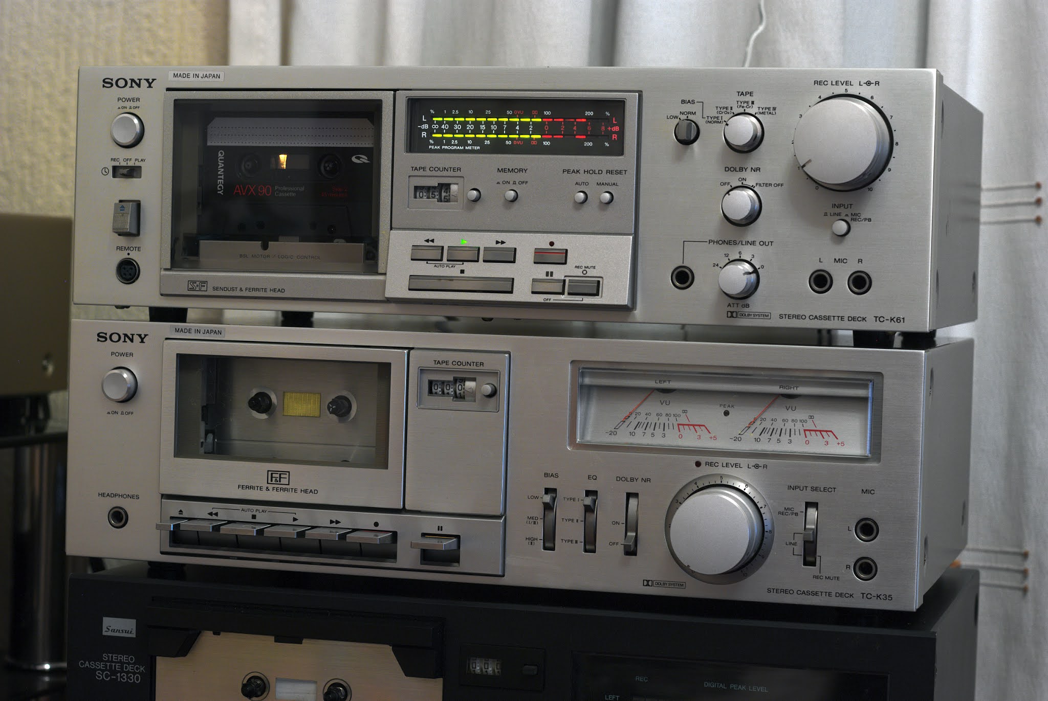
I bought a Sony TC-K45 off ebay which was advertised as 'For Parts or Not Working'. As it was very cheap (£15+postage), I took the gamble and purchased it. All credit to the seller who sent it in a large, well padded, and secure box.
 |
| Original Advert Picture for the TC-K45 |
I put a new 13A plug on the deck and inserted a 3A fuse then swiched on - the machine was basically working, however there are plenty of faults to be resolved.
The Cassette Transport System
Partially faulty ...
- Rewind/Fast Forward would not always engage,
- Play mechanism internally had been modified.
- Pause activates an auto stop after a few seconds.
TC-K45 Electronics
- Records - on the right channel only,
- Playback - will play tapes but very noisy, especially in the right channel, this is reflected by the meters at around -40dB/-30dB when in playback mode, without any tape in!
- Back lighting for the led meter had failed.
- Back lighting for cassette tape progress had failed.
Before I can even contemplate examing the electronics, I must first repair and so establish a working cassette transport system.
Fixing the Cassette Transport System: It's complex like any other cassette deck. I noticed that the previous owner has had problems with this deck - in particular activating Play.
The Play button is permanently 'off centre' as can be seen above, albeit by a small margin. On inspection, it appears someone has inserted and glued two small plates at the back of the Play button - I could only assume engaging Play had been a problem in the past? Indeed, it appears that a moving plate which is involved with the Play action possesses too much friction, meaning that when pressing Stop, this plate was not always returning to its ground state.
| At the rear of the cassette transport - Play action plate was not always returning to ground state. |
I suspect this plate is slightly curved, ie damaged internally - but how?
As a way of loosening this and other internal moving parts, I decided to squirt Servisol switch cleaner into the sliding mechanisms. This freed up the Play action, but there were still some minor issues regarding friction and getting the FF/RW buttons to latch once pressed, then return to their ground state after pressing Stop.
A solution to this was found - there is a 'release bar' which is tensioned by a torsion spring. One of the reasons for the overall failure of the controls is the lack of effective release bar torque, excessive friction, or both?
After another clean, this time with more directed Servisol and a little PTFE spray the release bar was able to rotate much easier, but still not as free and easy as new? However, this is as good as it will get - overall the mechanism is working much better than before, almost smooth and so almost 'as new'?
 |
| The small torsion spring that drives the release bar in circular motion. |
On the front side of the cassette transport, downward force compression leaf-like springs were distorted - due to earlier repair work reassembly? This is a very easy mistake to make as I experienced when disassembling the unit.
At the time of writing, the cassette transport system has now been re-installed, and is working very well. Both heads and capstan have been demagnetized, and the pinch roller cleaned. Playback of a 400Hz test tone indicated that the transport is stable. Play, and FF/RW are now fully operational.
| 68mm radius x 4mm wide flat belt seems to work. |
Fixing Playback Noise and Recording Issues
The source of the noise is not in the line amp stage, live monitoring of a source signal exhibits no audible noise. It appears to be in the replay amp stages - more to follow as I investigate.....
======================================
Is it the ageing and known noise-developing 2SC1345 transistor at the early tape playback stage?

The answer to the 2SC1345 question was 'yes', so a KSC1845FTA replacement was soldered in for both channels - ie Q101, and Q201; and also later Q102, Q105, Q202, and Q205.
The Q101, and Q201 replacements did eliminate the high levels of hiss, but now the sound was also distorted, and equal in both channels, so what next?
Line Muting Transistors and Circuits
I suspected that both line out muting transistors were not switching off properly.
Ideally when these transistors are in an OFF state, they mimic an open-circuit between signal and ground, ie high impedance between collector and emitter.
Examining these transistors at their respective base-emitter junctions revealed that when their bases were switched ON (ideally Vbe ~ 0.7), the base-emitter voltages were found to be Vbe ~ 0.71v (good!), but when OFF Vbe ~ 0.45v - this is too high. That is - when the transistors were meant to be switched OFF (open circuit between signal and ground), they weren't fully OFF, ie not an open circuit.
I have temporarily removed the muting transistors, and soldered in two 1MΩ resistors between each signal and ground point, ie between C-E.
Now that no transistors exist here, the Vbe voltages take on different values, because there is no conducting transistors - hence no voltage drops around the circuit, the Vbe voltages now are Vbe ~ 9.5v (ON), and Vbe ~ 0.48v (OFF).
The TC-K45 now works properly, no distortion in audio. I will try to rectify the improper working of line out muting later.

Record Head and Erase Head Alignment
As suggested above both heads were completely misaligned - it was immediately visually apparent.
There are two sets of alignments required for both heads, they are: azimuth and correct track height settings. There is no provision for head tilt with these decks.
Record/Replay Head
Some time ago I created a homemade 3Khz test tape at Dolby Level using my Nakamichi DR10. It's purpose was to act as a personal reference track height tape. It was this tape that I used to set the head height for my 'new' TC-K45. On one side of the head is the azimuth adjustment spring and screw, and on the other - a set of shims (less than 1/10 mm) to allow the technician to adjust the record/replay head height.
The process of head height is a slow and tedious job, but was completed without any obvious problems. It turned out that the original track height setting was correct to within minute margins.
Once track height was established, the final adjustment is to tweak the head's azimuth again. here I use a full track ABEX 10Khz azimuth reference tape.
Erase Head Azimuth and Height
I found myself having to reset this for the TC-K45 cassette deck. The only way I could manage to set these parameters reasonably correctly was to do a visual check with magnifier glasses and suitable lighting. I used markers on the cassette tape to set an azimuth for the erase head.
 |
| Erase head azimuth setting: Not a perfect solution, but adequate? |
LED Meter Display
The TC-K45 arrived without background lighting for the LED meters and the cassette tape. I've ignored the latter for now and focused on the meter display.
The service manual suggests that both lamps were wired in series and are supplied by 14.5v. I traced the circuit on the deck and decided to employ (eventually) two LED background lighting sources which would require small circuit modifications.
The 14.5v quoted in the service manual was approximately 16.5v open circuit, and about 15.8v under a typical 40mA load.
The modified circuit -

For the sake of completeness, I've included circuit equivalent elements. The 16.5v is the open circuit voltage from the power supply, and Ro is a Thevenin equivalent output resistance, which will be low, and not really worth calculating, but of academic interest: Ro = (16.5-15.8)/0.020 or 35Ω.
Calculating Rs
Applying Kirchoff's voltage laws around the circuit we obtain ...
16.5-Vd = Id[Ro+Rs]
or
16.5-2.8 = 0.02[35+Rs]
which gives ...
Rs = 685 - 35 = 650Ω
The LED is rated at 2.8v for a current Id of 20mA - this is for the quoted brightness. It's power dissipation will be ~ 2.8×0.02 or 56mW.
With a little bit of trial and error, I decided to make Rs = 690Ω
The LED was then carefully fitted into the deck.


Then ..

And finally, working ....

There are other minor issues to consider over the coming weeks, however so far - all is well! 👍
++++++++++++++++++++++++++++++++++
LED Lamp in Cassette Transport
Wired another LED in parallel for the transport with the LED from the meter display.
The revised circuit ...

| Now with cassette tape back lighting. |

Further Servicing Subjects to Consider
- Revisit the cassette tape transport mechanism/stability
- Line out muting fix
- Peak meter and time constant assessment, and recap.
- Power supply - recapping
- Replace other old transistors
- Voltage amplifier OP Amps NJM4560D seem fine, should I replace these?
Line Out Muting Fix
Replaced the old 2SC2001 NPN muting/switching transistors for new ones. There is still an excessive +0.45v at Vbe when line out is not muted - seems too high to me? Ideally, I want Vbe ~ 0.7v (Mute, ie not PLAY), and Vbe ~ 0.0v (PLAY).
Line Out Mute Switching Circuit
Zener Diode D314 Replacement
I initially had difficulty working out the logic of the voltages that made this circuit work. D314 is a 3.0v zener diode which in this context is seemingly never reversed biased into zener breakdown, but instead 'buffers' (when reverse biased) an approximate 2.5v dc 'Play' signal and so acts like a Norton constant current source with a very high resistance in parallel to to Q308 and R317 under these conditions. Similarly, a Thevenin model could also be used to model the circuit.
I also have a Sony TC-K35 deck which is very similar to the K45 circuit board and so can compare with. Yes, the D314 is never driven into current vs voltage avalanche conditions.

All line mute switching is now working well.
Recording Imbalance on to Tape.
Yet another malfunction began to surface was an apparent random imbalance in the recording levels delivered to the tape. This was very difficult to trace, as the deck would record correctly, until without warning - it would then record the source audio with a strong imbalance of approximately 6dB favouring one channel.
So a complete electrolytic re-cap was undertaken for both channels. It was not until a while later after recording and playback, did the fault occur again! It seems that the circuit had to 'warm up' before this fault would surface?
At this point my suspicions then turned towards the NJM4560D OP Amps involved in the pre-emphasis curve and general recording, in particular the left channel.
Luckily I had earlier bought some JRC4580D OP Amp replacements for this deck, and so immediately desoldered the IC101, and IC201 chips. In their place I soldered in two 8-pin DIL units, followed by the new JRC4580D units.


Desoldering is achieved very effectively when using copper braid.
So far the deck is running very well.
****************************
Recording and Play Levels Between Machines
One of the most difficult tasks to carry out successfully is to mechanically and electrically calibrate all our machines so that their record and playback levels match accurately.
Track Height Matching and Levels
I've had some difficulty in getting the TC-K45 to be fully record-playback-combatible with my other machines.
However, to shorten a long story I have decided to again 'tweak' the track height of the Sony TC-K45 to match my Nakamichi DR10 (like my other decks) as accurately as possible - this required the use of an extra fine shim.
How was this achieved?
Answer: by using the DR10 to create a 10 minute, 3Khz sinewave test tone on a quality blank cassette.
The Nakamichi DR10 serves as a reference track height creating deck, and also a reference for the magnetic width of both left and right tracks on the test tape.
Pre-calibrated DR10 Dolby Level recordings were also employed to calibrate the TC-K45 for Dolby Level.
************************************************
TC-K45 Record/Replay Head & Transport Issue?
Well, after much investigation, and patience (not to mention crazy determination), I have finally established a stable tape path. With both heads being out-of-line and out-of-azimith of the cassette standard, I have finally got the machine to record and playing back correctly. There were so many niggling problems surfacing as I attempted to understand what the errors were and how, if possible, I could rectify them.
In summary the transport exhibited poor tape-head-wrap issues, track height, and azimuth misalignments - this for both heads, not just the record/replay head!

I have some pozidrive 10mm/12mm M2 bolts and M2 x 0.3mm washers
on order - those pictures are just temporary, although 100% adequate.
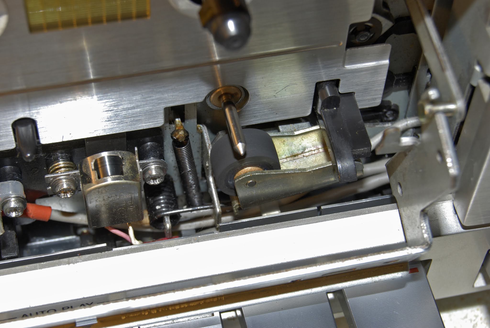
When pressing PLAY the head assembly would not always rise to the required height - something I didn't realize for a while until I noted poor head wrap, and a tendency to warp or crease tapes in a cassette shell without tape pads fitted. The reason - the original head assembly bolts were too long, and so interferring at the back with plate mechanism movement - this I later corrected. Now the TC-K45 offers good head-wrap - very important for tape sound stability and reliable erasure.
 |
| The improved tape-head-wrap and tape flow now allows me to make stable recordings without a tape pad fitted - which is exceptional for a non-dual capstan machine. |
 |
| Erase, and record head close up. |
*****************
New Head Assembly Screws

Now the TC-K45 records and plays back very well as far as levels are concerned, matching my other decks well. Final tweaking will be done later.
Disabling Auto-Stop
This is something I would not recommend anyone do, but part of the transport mechanism had developed a fault - the machine was attempting to auto-stop when the machine was sitting idle! Although presenting no problems, it was making a clicking sound periodically. So, to remedy this, I have disabled the worm drive that activates auto-stop until I decide to look further into the matter.
Transport Flutter
From the very start I had noticed flutter in the sound under certain musical passages - I'll also look into this later. 22/12/2020.
Pinch Roller
Carefully roughed-up the pinch roller with very fine emery paper, removed the excess rubber, then finally applied Rubber Renue to the pinch roller. Applied and cleaned with Q-Tips.

So far so good, been playing the deck for 2 hours now - all good, fingers crossed! 24/12/2020.
There are now just two outstanding issues:
(1) Pressing Pause activates an auto-stop,
(2) Auto-stop deactivated because of a minor mechanical malfunction. However, since I've muted auto-stop, the Pause action works fine!
Restoration Finished
For now I'll stop work on the TC-K45, as its working to almost 100% capacity.
On balance, I'm very pleased my persistence and patience has paid off. There were a few times when I thought of abandoning this restoration attempt earlier.
25/12/2020
Dolby Circuit and Muting (28/12/2020,1/1/2021)
Partially as an experiment, and also to be certain that - the always-on dolby circuit was not going to interfere when dolby was set to OFF, I decided to replace the 'old' but apparently working 2SC1364 NPN transistors with firstly - a set of 2SC2001s, then later a set of KSC1815s.
My attention turned to the better 1815 with high hFE at low Ic currents, and with theoretically - a low slope resistance (when ON) to act as an efficient signal sink to mute out any signals arriving seemingly to and from the dolby circuit when Dolby is set to OFF.
The one thing that struct me when I swapped out the old 2SC1364 for either 2SC2001 or KSC1815 was an L/R imbalance in the recording for both a dolby encoded signal and a non-encoded signal. Why was this?
I cannot fully answer that question, but it seems that my KSC1815 replacements (like the 2001s) needed a slightly higher Vbe ON voltage to respond sufficiently and so mute out dolby (when Dolby=OFF via DC switching), and allow the Dolby=OFF state to function properly, ie no interference with non-dolby recordings in playback mode. This doesn't fully answer the question, but the solution seems to have worked?
Previously: Vbe(ON) ~0.63v, now Vbe(ON) =0.67v with help from the additinal 68KΩ resistor (marked in blue) in parallel with 100KΩ. Base current at maximum ON state will now be ~ 8.5v/40KΩ or ~ 0.200mA.
Incidentally, if I wanted to remove dolby from the circuit completely, then I suspect I would have to to 'short' R128 - in much the same way as driving Q103/203 ON will also short-circuit R128 to signals. (Actually, later this is what I did, and yes, shorting out R128 did removed dolby completely when dolby was switched ON)
So far so good - both Dolby OFF and Dolby ON work well.
 |
| In use, it seems that Q103 acts as a 'dynamic resistor' in parallel across R128. Effectively dynamic filtering (ie Dolby B) being driven by the peak detection circuit of D102, D103, C124, R137 etc? |
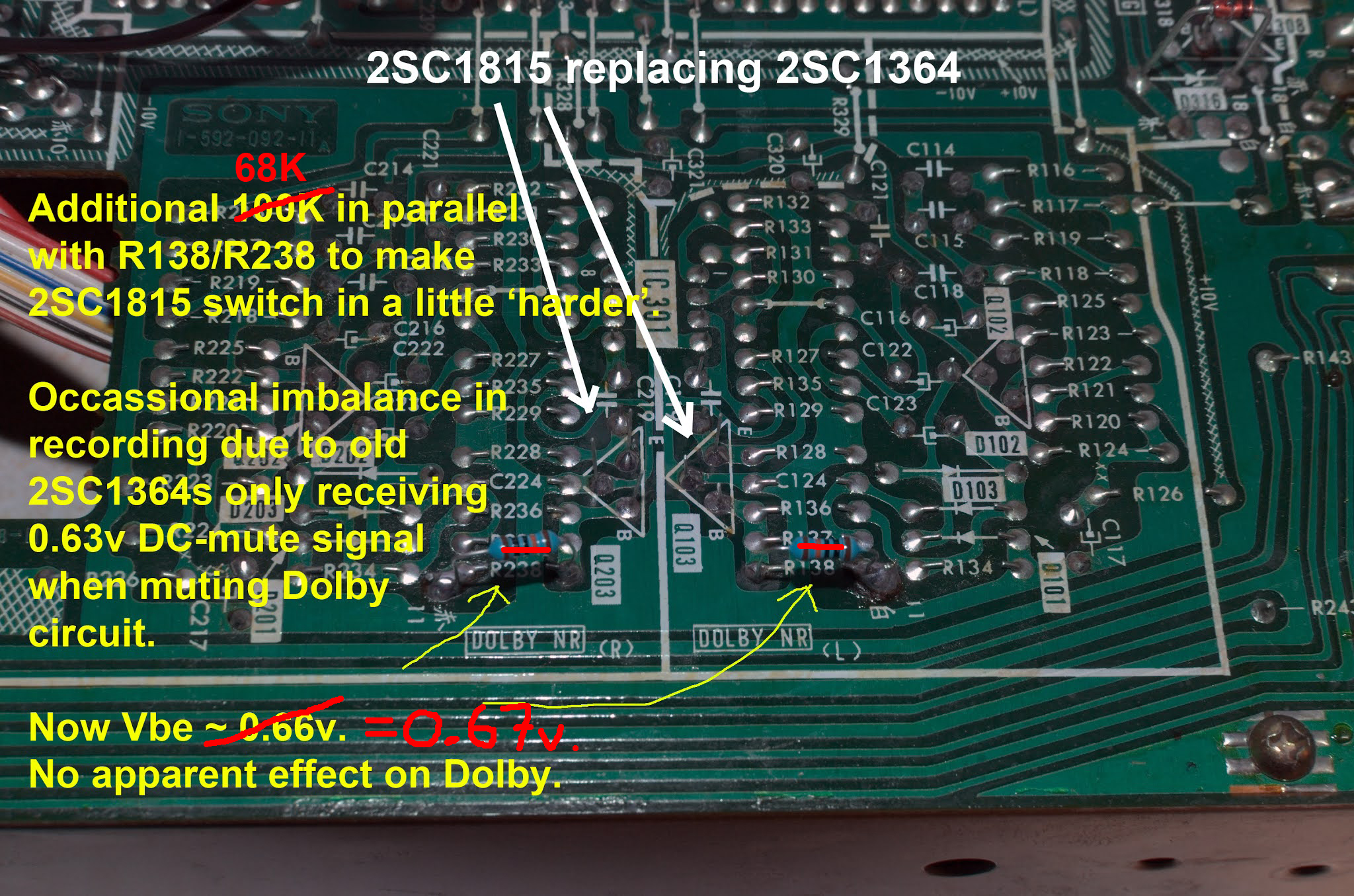
Note: This small circuit revision is ultimately an experiment - the lowering of R138/R238 should not interfere with the dolby processes. Should it go wrong, I'll revert back to the original circuit diagram, and transistors. However, so far - all is good! (29/12/2020)
Pinch Roller and Flutter
Only last night did I think about swapping the current pinch roller out of this TC-K45 for another old roller I had in stock. The result? - much improved sound with the flutter greatly reduced, but not entirely eliminated.

 |
| Replacement pinch roller, old stock. |
It's time I bought a new pinch roller! (31/12/2020)
15Hz Flutter Modulation and a Solution (02/01/2021)
The flutter mentioned above persisted, but only when the TC-K45 began to 'warm up''. Perhaps as little as 5-10 minutes would pass before flutter modulation would surface again.
Initially, I discredited the idea that the origin of this low frequency (approx 15Hz) flutter could be located from the motor itself? However, in desperation I decided to open up the deck again and remove the motor. At the time I also had the idea of replacing the 2400rpm CCW motor with a Mabuchi alternative complete with new circuit.
Once removed I also seperated the pulley from the motor spindle, and applied Servisol Super 10 down the motor shaft and inside the motor chamber as indicated by the arrows. Note: Servisol Super 10 switch cleaner is not WD40.
 |
| Left: Mabuchi 12v, 2400rpm CCW. Right: Sony's original with thicker spindle. |
The outcome? - the flutter disappeared, even when playing back a 3000Hz test tape I could not clearly pick-out flutter, I am very pleased!
Time will tell if this is a permanent solution - so far the TC-K45 is now a fully working cassette deck! 👍👍👍
This blog/article is now complete and so finished.
2nd January 2021.
______________________________________
21/11/2021
Playback Equalisation (De-emphasis) Adjustment
Recently I noticed that when recording material on the TC-K45, and then playing back the recording on another machine there was an imbalance favouring the right channel by approximately 2dB .. 3dB. I immediately suspected a recording and playback equalisation difference between left and right channels.Observing the service manual circuit diagram, playback EQ (called 'de-emphasis') can be trimmed by varying both R110 and R210. I was interested in setting both left and right channels to record, and playback equally on the TC-K45, but also on other machines.
The circuit modifications have allowed me to trim playback EQ for each channel equally, as they appeared to be unbalanced!?
I used a home made Nakamichi DR10 IEC 1981 equalisation tape which has been recorded with a frequency sweep from 333Hz to 10Khz.
Please note: This and other old Sony decks (1970s IEC EQ standard?) and the Nakamichi (probably IEC 1981) do not conform to the same record and playback EQ standard, I simply use this tape as a reference to compare all decks for their playback response at 333Hz (defined as 0dB) and then at 10Khz (usually -4dB, -5dB, -6dB, ... -10dB etc)
Originally, the TC-K45 playback response when playing the Nakamichi tape was ~ -9.1dB, and ~ -10.5dB at 10Khz, where 333Hz was the reference level, so 333Hz is taken as 0dB.
Inserting a new simple circuit modification to replace R110/R210 has allowed me to trim both left and right channels to the same output drop at 10Khz. And in the case of the TC-K45, this is now at about -8dB/-9dB.
I can of course make this 0dB ... -6dB, -7dB, -8dB, -9dB, or even -10dB, the choice is mine.
However, there is a trade off to be considered: less de-emphasis (less treble cutting on playback) and the amplifier's response shows a large rise (4dB .. 6dB) in upper midband frequency response, and general amplifier stabilty is slightly compromised.
The best playback EQ level at 10Khz seems to be around -8dB .. -10dB. The upper mid band rise is restricted to about 1dB .. 2dB.
Of course the bias frequency amplitude (just called 'bias') was then adjusted internally to allow the TC-K45 to record and playback a flatter frequency response from about 100Hz to 10Khz.
The Sony TC-K45 was then totally re-calibrated throughout.
Now?, playing TC-K45 made recordings on other machines now appear balanced.


OP Amp Instability
The physical environment in which an OP Amp 'lives' can affect the stability of the voltage amplifier.
Problems began to surface after I had cleaned the region where the OP was situated. The JRC4580D would almost randomly saturate with an output around ±9v! Mistakenly I was spreading tiny deposites of micro dirt and moisture (effectively a mild electrolyte?) about the region of the OP Amp - big mistake!
So, why was this instability happening?
Well, the answer was initially difficult to find as I over-analysed the circuit looking for reasons why the amp was oscillating or just saturating. However, the thought crossed my mind regarding the circuit board itself - is the board conducting slightly between the ±9v supply and the high impedance inputs?
The answer to that question was a definite 'yes'!
After cleaning the circuit board (solder side) with isopropyl alcohol, allowing to fully dry, then brushing off any potential debris, the OP Amp worked fine!
Please note - even my breath was enough to add moisture and a conduction path between the voltage supply and the input terminals V+, and V-.
As a precaution, I coated the solder side of the board with clear nail varnish; no solder-to-solder conduction. This process is called conformal coating of the circuit board, clear nail varnish was used here because it was a cheap and immediate solution.
No more instability. :o)
27/11/2021: Subject to alterations and corrections without notice.
- Inconsistent auto-stop operation,
- Pause action resulting in pause, but also triggering an auto-stop!?


 |
| For some strange reason the torsion spring was left in the wrong place, it was also 'trapped' there! The effect of this was to stop the Pause action from disabling the auto-stop mechanism. |
 |
| Rear view, all re-assembled and ready to go! |
 |
| I also had problems with the reel brakes, that has now been resolved. Plastic end-caps had come away from supporting sliding mechanisms (above in second picture) and had to be glued into place. |
Now everything is working as new, or maybe even better!


