The Sony TC-520CS
Thought I'd chance a purchase of this 'portable' cassette recorder made around 1976.
I was under no illusion about the deck, it's specification isn't high, but the price offered on ebay was worth the risk.
Primary Issues:
- Worn Sony PP128-3602C Record/Play Head
- Worn main drive belt.
- Dusty internally.
- DC Motor demanding too much current on PLAY, RW/FF etc.
- Noisy controls and potentiometers.
- Pinch roller had 'hardened' on one side.
Sony PP128-3602C Record/PB Head
The head was working in both channels but the wear was significant; so much so that extra back tension was required to hear playback clearly!
This reminded me of an old Sanyo M2000 cassette recorder I had many decades ago where I eventually had to change the heads.
The dilemma was either to get the head lapped professionally as there are no obvious direct replacements online, or seek another similar head.
The reader needs to be aware that this head's 'seating' on the platform is different to many similar replacements out there on the internet. The head is 'set back', where other similar heads are set further forward on the mounting platform.
Luckily I had a record head from a Sony TC-136SD 'parts machine' that was a direct replacement, although electrical characteristics appear to be a little different.
Pinch Roller
The old roller was taken out, and tapping out the 2mm pin prove easy.
The original was a 13mm x 8mm x 2mm roller; this was replaced with a 13.5mm x 8mm x 2mm roller that works perfectly. No clearance issues.
.jpg) |
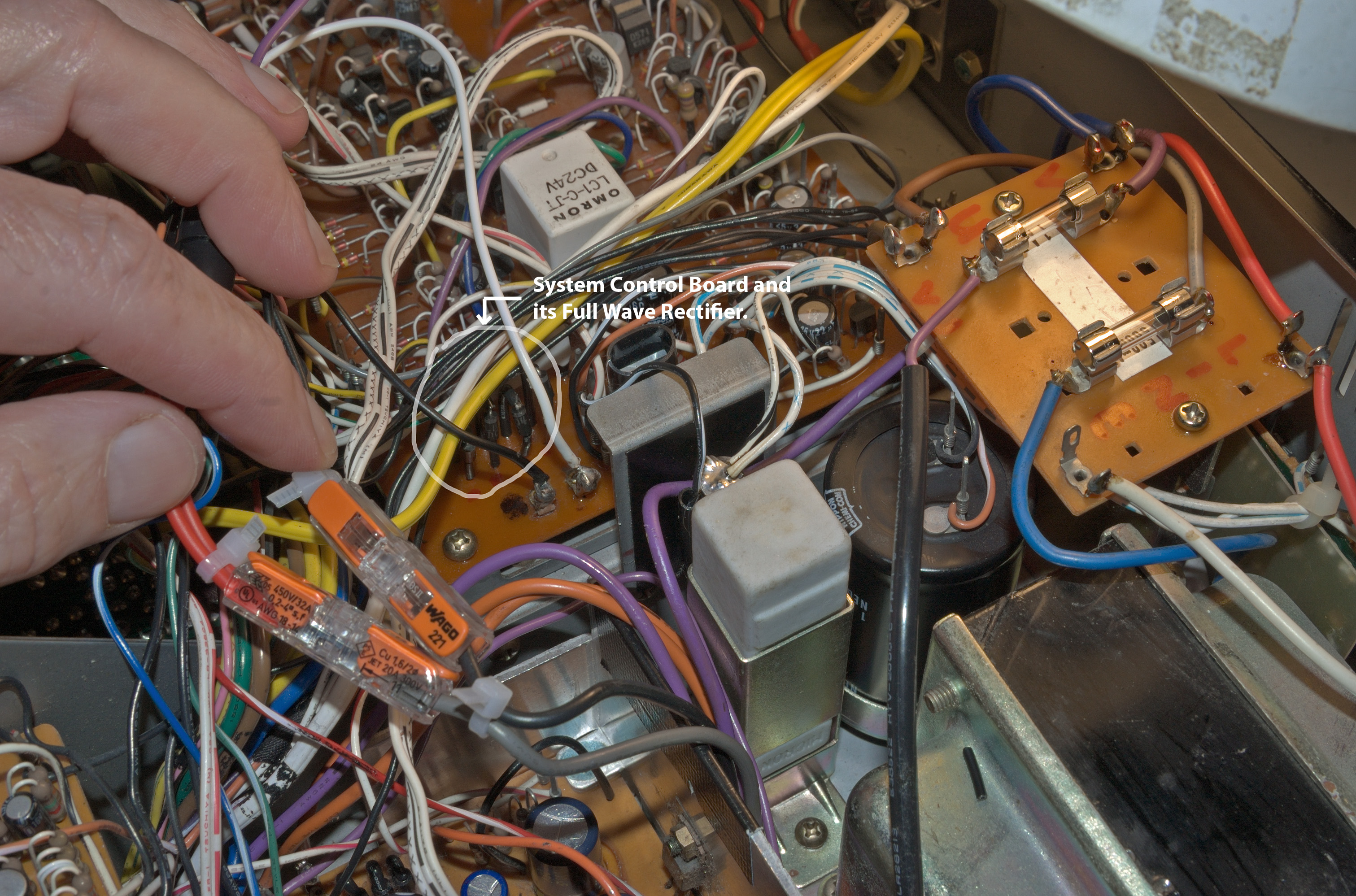
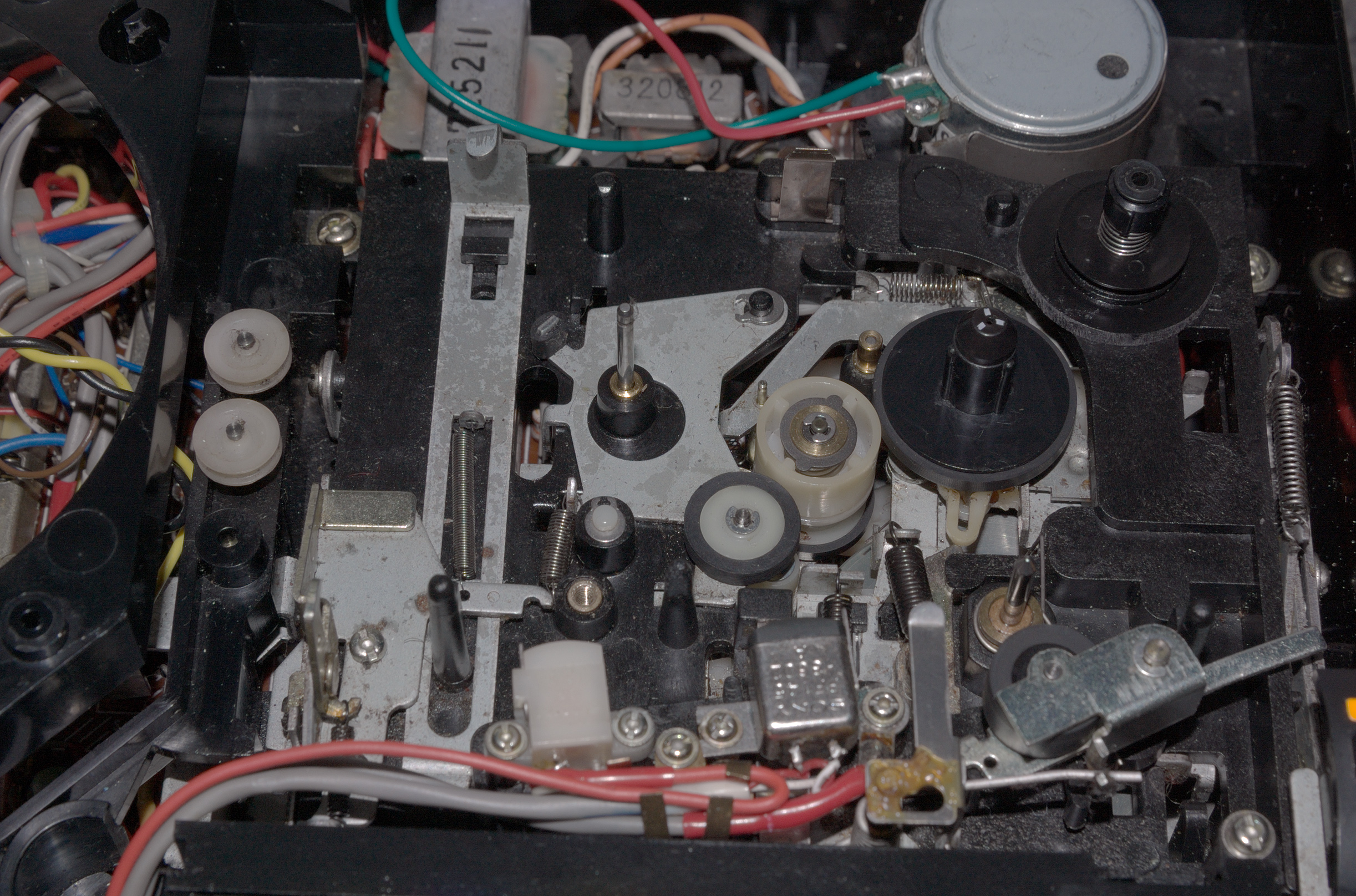
Photographed when the Sony TC-520CS was first opened up.
|
 |
| Showing Original DC Motor - top right. |
Later when a new roller and record head was fitted.
The rear of this version of the TC-520CS indicates that this deck was for the UK market, there are no multi-voltage selections available here.
DC Motor
The original motor's power is sourced from the smoothed 6v full wave rectifier, but without any voltage regulation. Indeed, there are no further circuits to facilitate DC motor speed control.
So then, what mechanism is employed to control motor speed when PLAY loading momentarily changes?
The answer to this is - the original Sony motor works on a centrifugal force principle to regulate motor speed. The only means to adjust motor speed was to open up the said motor and make careful adjustments to the motor speed governor. However, this is not recommended since this cannot be achieved without disassembling the motor every time; some centrifugal motors have an 'access window' so that speed adjustment can be made.
Tests also show that although the motor worked quite well (after cleaning the commutator), the current demand was at least 240mA during PLAY! Both RW/FF operations were much higher at 300mA and beyond. I've no doubt that this is well in excess of its design specification - perhaps the motor was momentarily stalling?
To compare this with another centrifugal motor I have in my stocks, the stocked item 'free running' current demand is only about 50mA.
Continuing on the subject of the original and somewhat high current demanding centrifugal motor system, I was initially concerned that the power supply was having to deliver excessive charge to the original motor, which would also increase rectifier mains ripple.
This centrifugal dc motor also induced additional electromagnetic interference into the audio chain, which was noticeable on playback.
A replacement was sought, and in my stocks I had a 2mm spindle DC motor which was previously employed on a Technics RS-630US deck.
Using a 'home made' 2mm to 2.5mm shaft diameter conversion, this worked well, but is rated at 9V and not 6V. Speed adjustment is very sensitive and as a backup I had bought some (2mm spindle) clockwise ('CW') Mabuchi EG-530AD-6F 6V rated motors and so later carefully fitted these hoping that the result would be equally good?
With the 'new' Mabuchi (Chinese copy?) motor fitted, PLAY current is around 90mA, and RW/FF approximately 150mA or more. These a little higher than expected, but nevertheless acceptable.
 |
An extra circular strip of high relative permeability
is spring-wrapped around the motor to
reduce motor noise interference. |
With the new Mabuchi motor fitted, speed control is facilitated by the internal potentiometer which is easily accessible. However, there was a drawback to this mechanical configuration - speed control wasn't broad enough. The minimal speed allowable is fixed at around 1.5% to 2% above the correct tape speed of 4.75 cm/s!
Why is happening?
The answer is simple - the original pulley diameter to flywheel diameter ratio (D1:D2) was set for the old motor, which did not run at 2400 rpm.
The recently fitted square belt has 1.2mm x 1.2mm cross section, and so a smaller 1mm x 1mm belt has been ordered. A smaller cross section square belt should lower the effective gearing ratio by an estimate of 1% to 3%. We shall soon see!
So far then, on order: 1.0mm x 1.0mm x 76mm square belt.
Autostop:
The auto stop system that Sony designed for this and other similar decks is not electronic, but is mechanical.
Within the system a worm drive is used, which is very low-geared. However, despite the low gearing, the collective torque load on the DC motor does increase periodically (approximately once per 3 seconds), so much so that a higher current-demand designed dc motor is needed for good speed regulation. Here the relatively small torque-current surge due to the auto-stop system would not affect the steady running of the motor, since the rise is largely 'buried' in an already high free running motor current. In addition, the brush to commutator contact area is generally larger thus keeping 'contact resistance' low as possible.
In audio terms, the current Mabuchi EG-530AD-6F dc motor and servo struggle to maintain a high degree of speed regulation, and so it is quite possible that the auto-stop mechanism will have to be disengaged later?
This every-three-second speed drift does not show up in wow and flutter figures since the 'wobble' is of very low frequency, possible 1/3 Hz? Nevertheless, it is perceivable on certain types of classical music.
As an example of the speed 'wobble', the ABEX 3.15Khz test tape can deviate as much as 5Hz to 15Hz every 3 seconds. In contrast to a average deviation of 2Hz, or 3Hz at worst!
Wow & Flutter:
The original specification for this Sony TC-520CS portable cassette recorder quotes a 0.26% (RMS weighted) wow and flutter figure.
The smooth running of the new Mabuchi motor, together with a suitable fitting drive belt yielded dramatically lower wow and flutter figures.
Power Supply:
The following only applies to the UK version.
New Square Belts Fitted:
Just fitted a 1.0mm x 1.0mm x 77.5mm square belt, then removed the autostop belt, and we have a 'transformed' Sony TC-520CS. Correct speed within tiny margins is now attainable.
Removing the autostop belt lessened the sporadic speed variations due to the every-three-second autostop generated speed 'wobble'.
I strongly suspect that belt thickness does indeed impact on the 'wobble' when the autostop loading periodically increases belt tension, then releases it; is a 'stiffer' belt is less likely to flex during this time? However, a thicker square belt does tend increase wow and flutter. Which, in my opinion, is the reason why most manufacturers eventually opted for flat drive belts.
With a ABEX 3.15Khz reference tape inserted, WFGUI playback data suggests the very low frequency speed wobble is as much as 12Hz, and sometimes more. I have no choice at this moment other than to use a narrower square belt to get the PLAY speed down to acceptable levels.
The danger of not having autostop means no autostop for PLAY/RW/FF etc, but an additional risk that - if the take up spool fails to turn (for whatever reason), then there will be an unpleasant tape jam into the capstan to pinch roller line. However, the take-up spool is driven by the main drive belt and looks very unlikely to fail.
Speed Drift & Wow/Flutter:
Speed Drift with auto stop coupling ...
Speed Drift without auto stop coupling ...
Note: ±10Hz drift is approximately ±0.3% drift.
Wow & Flutter without auto stop coupling ...
Mean wow and flutter now under 0.08% wrms.
Supply Spindle
The supply spindle is 'capped' via a push-on 'end cap', but this lost its ability to fit securely when returning it to the spindle. A 1.5mm e-clip was then used as a substitute.
(24/02/2025: Corrections and additions may follow where and when necessary)
cassettedeckman@gmail.com


.jpg)


.jpg)


