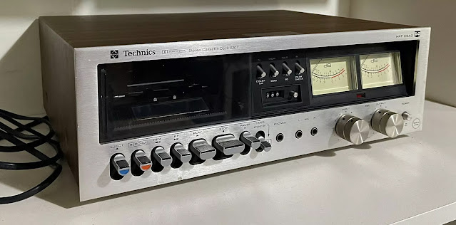
Technics RS-630TUS Cassette Deck
Lots of little issues with this 'faulty' deck that I bought off ebay. Cosmetically, it is in good shape.
Problems -
- Stuck sliding door.
- Stuck Front Panel Switch
- No mains plug.
- Worn pinch roller.
- Slightly slippy belt. (Measures approx 86mm diameter x 3.5mm width)
- Playback amplifier sporadic oscillations, mainly in the left channel.
- Dust in cassette mechanism.
Most of the above were easy to correct, however the main concerns were - reliable transport functioning and the sporadic oscillations from the playback pre-amplifier.
Pinch Roller & Transport
At first the thought of replacing the pinch roller looked daunting, but later realised that the 2mm internal pin that holds and guides the roller could be tapped through from the bottom side.
Here's how - very carefully break the plastic cap at the dead-centre point with a very fine drill, screw driver, or punch (~ 1mm diameter or less), this produces a small opening, and then very gently 'tap-out' the steel pin.
A 13mm or 13.5mm diameter pinch roller will work, but a 13.5mm diameter roller is recommended as this will give a slightly higher pinch-to-capstan pressure.
 |
| My initial attempt cracked the underside of the support for the pinch roller. The strength of the assembly was not compromised, but still I re-enforced areas of importance. |
The torsion spring that provides the pinch-to-capstan pressure is slightly puzzling. According to the Service Manual, the torsion spring is fed with its longer tail to the right as we look down on to the transport mechanism.
However, observing some online pictures, when in situe, the torsion spring needs to be tensioned like that indicated in red.
I have attempted to set up the tension like so, but found it extremely difficult, even with tools made for this kind of work.
So another solution was found.
The torsion spring is first centred underneath on the plastic pinch roller mechanism, and selecting the highest torque by 'pinning' the leftmost (shorter) spring arm into the relevant guide (hidden in this picture) should be done before returning the mechanism to the main board guide. The rightmost part can be secured into a groove provided by the Pause sliding parts.
Upper Left Side: This frontside view shows the torsion spring fully located - the short side of the torsion spring is tucked on to the underside of the roller swivel mechanism (as normal), and the longer tail is tucked into a Pause mechanism slot.
To increase working torque exerted by the torsion spring - first, the spring has to be carefull bent to increase effective torque.
To increase working torque exerted by the torsion spring - first, the spring has to be carefull bent to increase effective torque.
Factory Torsion Spring Positioning
I may at a later date try again with the spring in its factory default set up, but the spring will have to be bent again allowing me to tuck the shorter side under the roller assembly arm.
Auto Stop Problem
This would not activate, and the reason was quite simple - the spinning rubber idler tyre was not turning with sufficient force to activate the autostop.
This idler works off the brass knurled section of the capstan/flywheel, and was currently providing too much slip. The idler was 'roughed' with emery paper, and later cleaned with Rubber Renue.
Both autostop, and take-up torque are now functioning correctly.
 |
| Shown here is the autostop at the point of being triggered. |
It is worth noting that the autostop is only triggered for Play/RecPlay action, and not for rewind, or fast-forward operation.
If I have another criticism to make it is that the autostop will not be triggred if the take-up spool fails to turn, or lacks enough torque to turn the cassette tape reels.
Pinch Roller Tensioning - Again!
I finally decided to return the torsion spring back to its intended postion. I was always aware that its new postion could cause some small mechanical intereference.
The task was made easier by first bending (deforming) the torsion spring until it formed a new starting point angle. This means that the effective spring torque when setup would be less, but no less sufficient.
This made the return of the spring easier, but not easy! To keep the spring under control, I employed two pieces of tied string to keep the torsion spring stable in its position until I was able to release the long end into its target anchor point.
New Drive Belt
The previous drive belt measured approximately 86mm in diameter, and 3.5mm in width.
I fitted a few belts of different diameters and widths, but for better performance an 82mm diameter x 3mm width was best, and yielded the lowest (so far) wow and flutter figures. Wow & Flutter is averaging at 0.11% weighted rms (Japanese Standard JIS) figures.
The latest 0.11% wrms figure in green was achieved after the DC motor had been disassembled and cleaned with Servisol Super 10. The earlier figure in red was before the DC motor was cleaned, and also includes a larger 85mm x 5mm wide belt.
The latest 0.11% wrms figure in green was achieved after the DC motor had been disassembled and cleaned with Servisol Super 10. The earlier figure in red was before the DC motor was cleaned, and also includes a larger 85mm x 5mm wide belt.
 |
| Initial Wow & Flutter Figures with New Belts |
Clearly the better figures are in green, but a noticeable trend of increasing wow and flutter was noted over this approximately 9 minute period. This will be investigated later.
Playback Sporadic Oscillation
There were sporadic oscillations of high frequency, mainly in the left channel on playback. The exact cause of this is uncertain, but applying switch cleaner to the Play/Record multiswitch, and 'working' the Record ON mechanism solved the problem. Since then, oscillations have only occasionally returned, but are soon stopped once the Record multiswitch is 'worked' again.
Record-Play Switch
A serious attempt was made to stop these occasional bursts of instability, and so the record/play switch had to be completely disassembled as one line of enquiry.
This was de-soldered from the main audio board using a de-soldering station. Make no mistake, this is quite a time-consuming job.
This was de-soldered from the main audio board using a de-soldering station. Make no mistake, this is quite a time-consuming job.
In the end, the result was positive, so far - no more oscillations.
 |
| Contacts - All Cleaned. |
Bias Notes
On the front panel of the RS-630TUS deck are switches for bias and equalisation. It is quite easy to select a high bias for a Normal (Type I) tape, but of course using the default 120µS playback equalisation, or a 1326Hz 'Corner Frequency'.
On the front panel of the RS-630TUS deck are switches for bias and equalisation. It is quite easy to select a high bias for a Normal (Type I) tape, but of course using the default 120µS playback equalisation, or a 1326Hz 'Corner Frequency'.
Currently, with the deck in its present state, a high bias record setting gives a frequency response from 30Hz to 14Khz at -3dB at either end, reference 0dB at 1Khz, from a TDK D46 Type I tape.
The selected high bias switch is insufficient for Chrome or Type II tapes in my opinion - there is too much distortion, any Chrome tape on this machine will be under-biased. I shall modify the circuit later and report back on this.
Front Panel Switches: Dolby/Bias/EQ/VU Metering
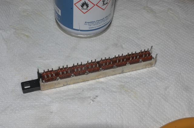
It was obvious that the action of the VU peak meter switching was inconsistent, and as a precaution since this deck is old, all four DPDT switches were removed. First desoldered, disassembled, and cleaned of long time oxidation and and accumulation of dirt.
It was obvious that the action of the VU peak meter switching was inconsistent, and as a precaution since this deck is old, all four DPDT switches were removed. First desoldered, disassembled, and cleaned of long time oxidation and and accumulation of dirt.
 |
| Before de-soldering |
 |
| Switch taken apart. |
 |
| All four switches returned |
So far only the power supply unit and those electrolytic capacitors involved with the VU meters have been updated.
DC Motor & Controller
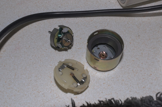
The DC motor and its controller circuit was opened up again, this time the brush and commutator design was investigated.
The commutator is a a little unconventional for this type of motor - in my opinion better than other simple DC motor designs. Here both commutator and brushes were cleaned, the former was cleaned first with a Q-Tip and switch cleaner, but later on with a little metal polish, then 'finished off' with switch cleaner again. Both ends of the motor shafts were lightly oiled.
Revised Wow & Flutter Figures
I was curious to see if any improvement could be made to the previous wow & flutter figures? To my pleasant surprise wow & flutter was reduced to a mean value of about 0.097% (JIS WRMS).
I was curious to see if any improvement could be made to the previous wow & flutter figures? To my pleasant surprise wow & flutter was reduced to a mean value of about 0.097% (JIS WRMS).
Speed Stability Revised
Casually, speed drift was examine over a period of about 14 minutes. Very pleasing results so far.
{Article unfinished, and also subject to changes and corrections.
16/10/2024}


