Sony TC-161SD (Later Model)
11/04/2022
A few weeks ago I bought another TC-161SD for 'spares' but then found that this machine had a different capstan flywheel design - very similar, if not identical to that employed on the later 'flagship' TC-177SD!
I soon realised that this deck was too valuable to be used for 'parts' only!
 | |
Flywheel system of the later series of the TC-161SD. The motor pulley and flywheel are connected via a flat belt, not a square belted system |
 | ||
This initial photograph shows the original motor start/run capacitor - which can be seen top right corner. |
Old Record/Replay Head
The deck was riddled with problems, mainly mechanical and possesed a record/playback head that appeared to be 'open circuit' in the left channel.
Taking the old head out of circuit did confirm that only the right channel was operating, while the left channel appeared to be open circuited! The head was now useless.
In the meantime I replaced the motor start/run capacitor, and later re-capped both the power supply and the auto-stop circuitary.
Replacement Head
The next task was to replace this with a third-party head.
I have a small stock of NOS heads, 'New Old Stock'.
The inductance of the replacement head is around 167mH, the TC-161SD's (~85Khz) bias voltage was currently around 31v peak.
Bias Currents
The new peak bias current will sit around 31/(2*3.142*85000*0.167) or ~ 347uA. Compared to 31/(2*3.142*85000*0.175) or ~ 331uA when the original PF145-3602's was in circuit.
These bias currents are tiny and virtually the same for either head. The audio current signal sits on this 85Khz bias 'carrier' is so small it will hardly register.
Please note - I've neglected head resistance in the calculations, as the inductance will dominate the value for the impedance at 85Khz.
New Head Mount
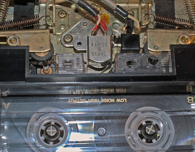
The NOS head was mounted on the original Sony head platform, but I had to first drill-out two head position locators which were employed to position the head correctly.
Both the old platform and the new head had their 'mating' surfaces 'roughed up' using 400 grit emery paper. Later the two were glued into place using Gorilla Glue, which 'cures' over a period of 24 hours. The two halves were held together 'still' under light pressure in a small vice - alignment was critical.
Alignment here being - that the head face and movement would be normal (90°) to the direction of the tape, and that the head stroke (depth) when Play was engaged, would not be excessive. Note - head height, tilt (zenith), and azimuth can be independently adjusted later.
 |
New record/playback head secured on to the old platform. |
 |
The cured glue can be seen in its expanded state. The glue also ran through the two drilled holes - out of shot. |
TC-161SD Head Assembly
 |
New head in operation. Fully aligned - head height, tilt, and azimuth. Excellent transportation. |
************************************
11/04/2022: This blog/article is unfinished .....
Pre-emphasis Change (04/12/2022)
Re-reading through this article again I soon realised that I had not modified the pre-emphasis curve for this later version of the TC-161SD cassette deck.
At some later date I hope to write up why I needed, and how I was able to reduce recording pre-emphasis for this and many other decks.
However, for now, here is the modification for this machine:
However, for now, here is the modification for this machine:
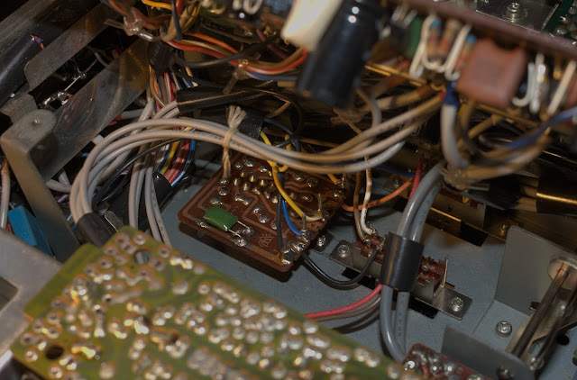
To access the pre-emphasis (Normal/CrO2) switch board, six screws and their respective switches had to be removed from the top side of the tape deck.
Result: success!, the TC-161SD delivers nice clean voice sibilances and treble!
After this job was complete, the usual checks were made to ensure that previous playback levels and record levels had not changed?; they hadn't!
After experimenting with the recording bias for both left and right channels by subjecting the recorder to white noise at about -20dB (or a little higher), I can report back that the frequency response for this 1972/1973 design deck on a 1980s TDK D C90 tape was slightly better than 40Hz ... 15,900Hz/16,500Hz at -3dB, left/right channel respectively. Reference: 1000Hz.
Random Induction Motor Images
13/06/2023
New Drive Belt: With a 110mm (diameter) x 5mm (width) belt fitted, wow and flutter as measured on WFGUI.EXE measure somewhere between 0.045%-0.075% Weighted RMS.
cassettedeckman@gmail.com
cassettedeckman@gmail.com


