AKAI GXC-760D
Taken from the Original Advert
I was determined not to buy another cassette deck!, and then this AKAI GXC-760D 'tank' popped up on ebay. Advertised with a fault, the more I looked at it, the more I drooled over this 1976 classic model.
While repairing this AKAI GXC-760D some unknown short-circuit electrical problems were yet to be addressed, but first - a sticking door problem, and a set of very inert pinch roller mechanisms had to be fixed first.
The roller mechanisms were 'freed' using acetone, OD41, switch cleaner, and some heat from a soldering iron. It was the heat that accelerated the removal and cleaning of the complete mechanisms.
Some photographs ...
The supply roller (near centre pivoted) mechanism could have been lifted off its support post, but that would require that the erase head is temporarily removed. Since there is a height adjustment for the erase head, this was left alone. The supply roller mech was freed with solder iron heat and switch cleaner, and it movement is as 'free' as the take-up side.
Regarding the sticking door issue, I forgot to photograph the issue, I just went ahead and got to work on it.
Supply Tape Guide
This is height adjustable, and should be returned, and adjusted using a Mirror Cassette - ideally the tape 'sits' head centre of the guide.
Ultimately, it is the internal cassette shell rollers that set the path, the guides, and dual capstan and pinch rollers merely 'stabilize' tape movement.
Before any final calibration is performed on the deck, both tape guide, and Rec/PB head height will be carefully set. At this moment, I've no concerns about either of these parameters being 'out of alignment'.
Later tests reveal that tape playback, and recordings are excellent on this machine. As is transfer to, and from other calibrated machines.
Source of a Short-circuit after Switch ON
Of course the short-circuit which blew the transformer primary winding 500mA fuse after the machine was switched on, could have been almost anything, but I put it down to a few possibilities.
- Transformer internal short circuit (very unlikely)
- Full wave rectifier 'short', where one or more diodes had become effectively a short-circuit internally and not a one directional semi-conductor anymore. (likely)
- Induction motor, or motor servo short-circuit (possible, but unlikely)
- Incorrect internal wiring. (possible, but unlikely)
- PSU electrolytic capacitor internally 'shorted'. (possible)
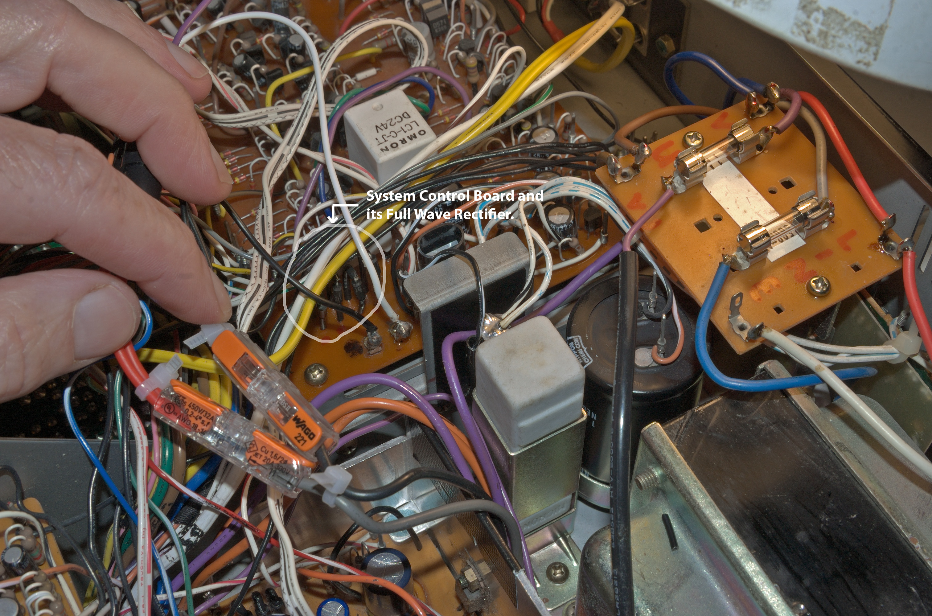
Since the previous owner had already re-capped the PSU, the latter possibility was dismissed. My focus was on the possibility of a full wave rectifier failure.
And indeed, this was confirmed, but the problem was not to be found in the main PSU, but the System Control board.
A possible scenario is suggested below -
Splitting the secondary transformer winding of 95v (quoted) into two phases: phase A, and phase B, a short circuit is then possible on the second (negative) half, or during phase B.
Eventually, the old diodes were removed and tested - one was found to be conducting in both directions, so my diagnosis was correct, although I initially suspected this to happen within the main PSU.
The diagram above shows new 1N4004 (400v reverse breakdown rated) equivalent diodes populating the full wave rectifier on the System Control board.
Some modifications were also made to the distribution of the 95v (ac) secondary supply.
Original faulty diodes -
Fusing the SYSCON and the Motor Servo Circuit
As a way to isolate potential future issues, both circuit boards were fused with 200mA quick blow fuses. This is indeed not strictly necessary, but it does permit easy measurement of system currents during the operation of the GXC-760D.
The addition of these in-line fuses does increase the 'chaotic' look to the deck, but it will be tidied up later.
Operational Load Currents
Investigating the current demand during the 'free-running' (motor with no PLAY/RW/FF load) conditions, and during PLAY, we have:
- Primary Winding AC Current: Free-running ≅ 110mA, PLAY (solenoid) ≅ 187mA, RW ≅ 126mA, FF ≅ 118mA
- System Control Board: Free-running Motor ≅ 10mA, during PLAY/Solenoid action ≅ 106mA
- Motor/Servo Board: Free-running of Motor ≅ 76mA, during PLAY ≅ 90/92 mA
- Power Consumption: The highest power or even 'VxA' consumption is generally during the state of PLAY, it is approximately 230v x 0.187amps or 43 watts. This figure will include transformer resistance and magnetisation losses.
All the above figures are in line with what is expected.
Induction Motor Belt Slippages
After cleaning the motor pulley and belt, the belt began to slip to one side during start-up. What was happening?, clearly the belt was slipping in some way, its overall tension was good.
Later the brass pulley was carefully and gently 'sanded' with fine grit paper to help remove all old rubber residue, and the the problem of belt slippage was eliminated.
Pending Jobs
(1) New 'Motor Run' capacitor? (Yes, later)
(2) New belt?, although the 'old' belt is working fine. (It is about 5mm or 6mm in width. (Diameter not measured yet)
(3) Investigate the condition of the Reel Motors, although no obvious problems have surfaced.
(4) New electrolytic capacitors for all boards? (Probably not generally needed, an over-rated exercise in many cases)
(5) Re-transistorise boards? (Not yet, may leave this until required)
(6) Populate both Motor Servo and main PSU with new rectifier diodes (Yes, probably later)
(7) New pinch rollers? (In theory yes, but currently no issues at all. Both have been treated with Rubber Renue)
(8) Assess induction motor and flywheel, then lubricate? (Yes, pending)
(9) Assess both SM and TM (Supply/Take-up Motor) brush and commutator wear? (Yes, later, no problems at this moment)
More potentially to follow ...
A Working GXC-760D
 |
| Long Exposure Photography |
Corrections, and amendments will be made without notices.


.jpg)


